
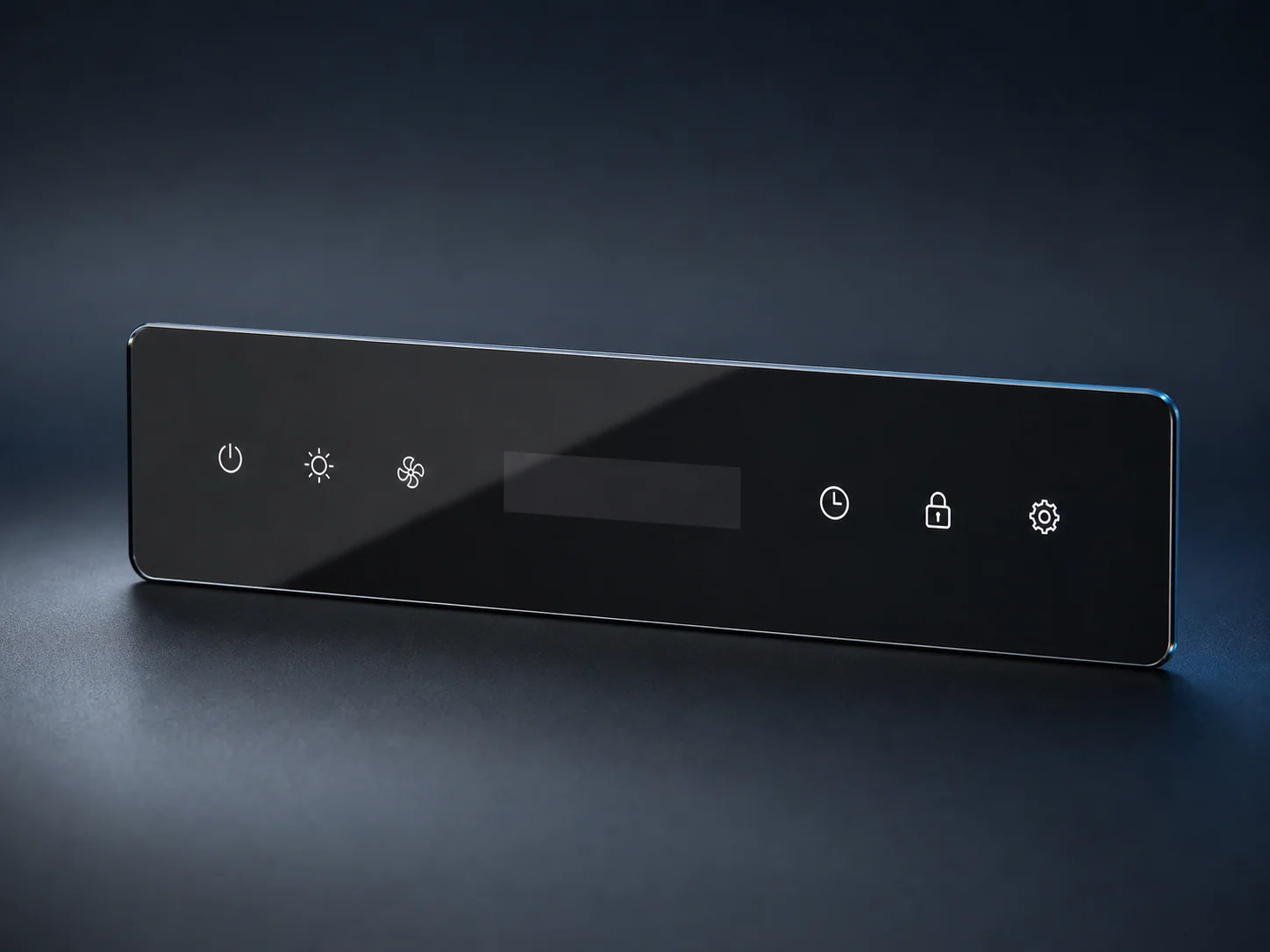
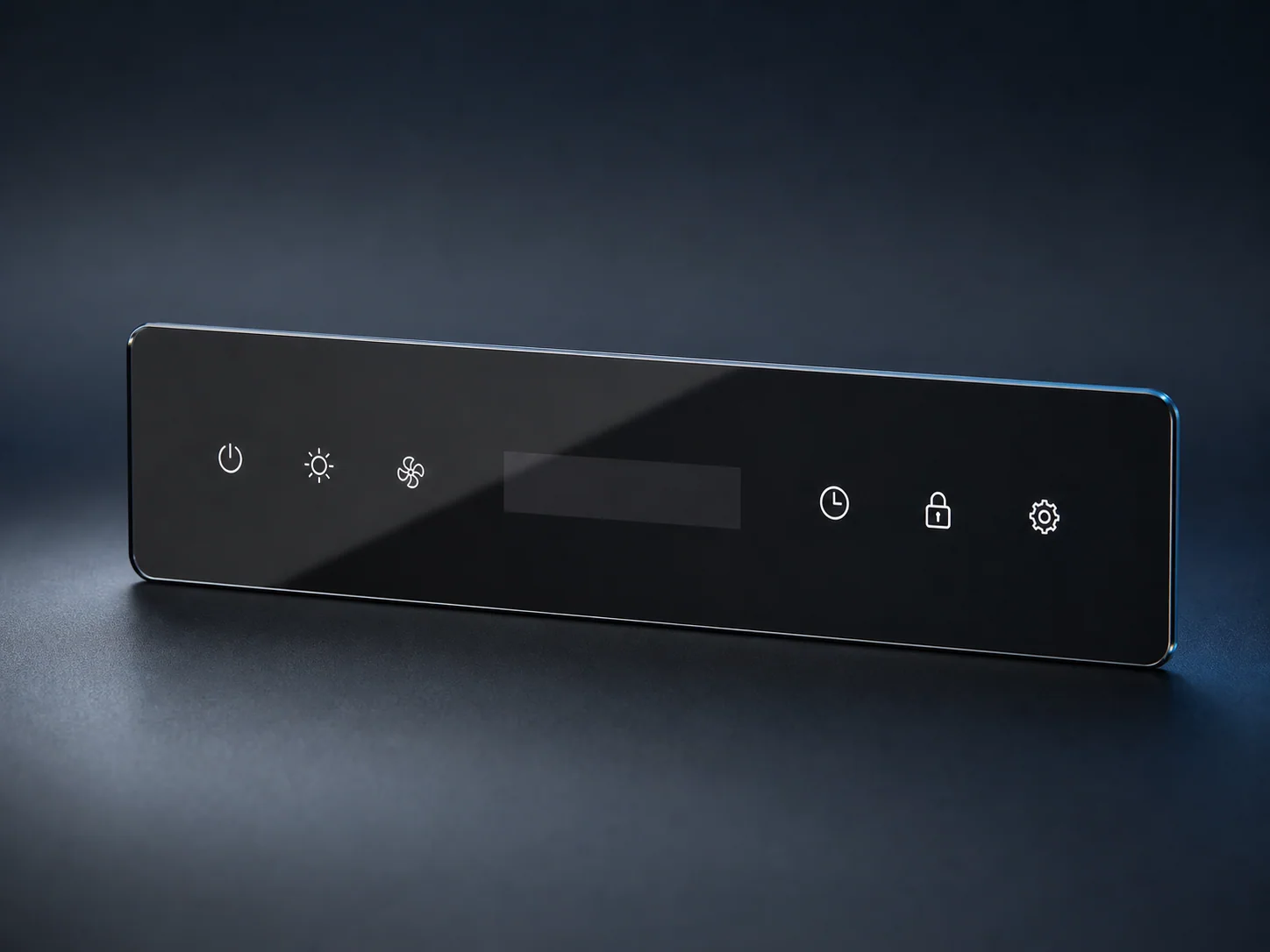
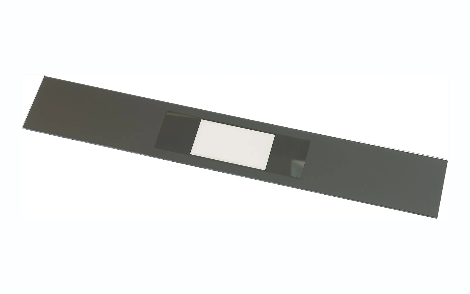


Capacitive touch through glass works when the complete interface is engineered as a stack, not when a printed glass panel is selected in isolation. Overlay thickness, dielectric properties, ink, adhesive, air gaps, electrode geometry, grounding, firmware and the use environment all influence sensitivity and false activation.
For an appliance OEM, the glass supplier can control the cover panel geometry, edgework, printing, optical windows and agreed surface treatments. The electronics team must design and tune the sensor system behind the production-intent glass. Reliable performance is confirmed on the assembled HMI under realistic moisture, temperature, noise and user conditions.
This guide explains what mechanical, optical and process information should be shared between the appliance engineer, touch-controller designer, glass manufacturer and assembly supplier.
Quick answer: how do you design capacitive touch through glass?
Use the following sequence:
- Define the user, environment and required controls.
- Freeze the glass material and thickness range early.
- Document every layer between finger and electrode.
- Eliminate uncontrolled air gaps.
- Keep conductive ink or coating away from touch fields unless intentionally engineered.
- Coordinate button size and spacing with overlay thickness.
- Align printed icons, electrodes and assembly datums.
- Validate the display and touch functions together.
- Tune electronics on production-intent assemblies.
- Test moisture, cleaning, gloves, temperature, EMC/ESD and manufacturing variation as applicable.
- Control glass, artwork, adhesive, sensor and firmware revisions.
- Revalidate when the stack changes.
Do not approve the glass appearance and touch function as unrelated activities. A change that looks cosmetic can alter the electrical stack.
1. Define the HMI use case
Begin with the customer interaction rather than a generic “touch panel” requirement.
Document:
- Buttons, slider, wheel or proximity function.
- Finger, gloved-finger or stylus use.
- Dry kitchen, humid laundry area or exposed equipment.
- Expected water droplets, steam, grease or cleaning fluid.
- Required response through normal contamination.
- Control spacing and accidental-touch risk.
- Audible, visual or haptic feedback.
- Display and indicator behavior.
- Applicable appliance safety and EMC requirements.
A microwave control fascia, washer lid and outdoor charger do not share the same environment. Their overlay and electronics may all use capacitive sensing, but their test plans should differ.
Decide what failure means
The risk assessment should distinguish:
- Missed touch.
- Delayed response.
- False touch.
- Adjacent-key activation.
- Continuous activation.
- Loss of response after moisture or temperature exposure.
For safety-related commands, the appliance designer should determine whether additional confirmation, lockout, mechanical control or other mitigation is necessary.
2. Treat the interface as a material stack
A simplified stack may contain:
- User finger.
- Glass cover.
- Decorative or masking ink.
- Adhesive, spacer or optical bonding layer.
- Sensor electrode on PCB, flexible circuit or transparent film.
- Ground, display and surrounding electronics.
- Mechanical support and enclosure.
Each layer affects the electric field and assembly repeatability.
Texas Instruments’ CapTIvate design documentation describes the overlay as an important part of touch performance and notes that material and thickness affect sensitivity. Infineon’s CAPSENSE guidance similarly treats overlay material, thickness and air gaps as system design variables.
Primary references:
These component-vendor guides help explain electrical principles. The OEM should still follow the selected controller’s current documentation and validate the actual appliance.
3. Freeze overlay material and thickness early
Glass is attractive for HMI overlays because it is non-conductive, rigid, cleanable and visually consistent. However, changing thickness after sensor design can change sensitivity and require electrode or firmware adjustments.
The drawing should define:
- Glass family.
- Nominal thickness and permitted variation.
- Strengthening condition.
- Coatings on either surface.
- Print layers and their orientation.
- Bonding layer.
- Maximum expected gap to the electrode.
TI’s guidance gives a typical overlay range for particular CapTIvate touchpad designs, but that range is not a universal appliance rule. Suitable thickness depends on the controller, electrode size, stack and required environment.
Consider the real dielectric stack
Do not calculate from glass alone. Ink, adhesive and any air gap sit in series between the finger and sensor. Their thickness, dielectric behavior and coverage can affect performance.
Air has a lower dielectric constant than glass or many bonding materials. Both TI and Infineon emphasize avoiding uncontrolled air gaps. A nominally thin stack with a variable gap may perform less consistently than a slightly thicker but well-controlled bonded stack.
4. Control air gaps and mechanical support
Air gaps can result from:
- Panel bow.
- Uneven adhesive.
- Foam compression variation.
- PCB warpage.
- Incomplete contact around a display.
- Dust or particles.
- Housing distortion.
The assembly drawing should define support locations, adhesive geometry, spacer thickness and allowable compression. If the PCB is pressed against the glass using springs or foam, document the force and tolerance range.
Avoid local stack changes across a button
A touch key should not sit partly over adhesive and partly over air unless the electronics are designed and validated for that construction. Keep the material stack under each electrode uniform where possible.
Review service and aging
Adhesive creep, foam relaxation, moisture ingress or repeated thermal cycling can change the gap over time. Include aged assemblies in validation when the application risk justifies it.
5. Coordinate electrode geometry with the glass
Electrode design belongs to the electronics team, but the glass drawing provides important inputs:
- Overlay thickness.
- Button icon size and position.
- Spacing between controls.
- Nearby display windows.
- Conductive coatings or metallic decorations.
- Grounded frame proximity.
- Edge distance.
The touch-controller supplier’s design rules should guide electrode diameter, spacing, guard structures and tuning. Do not assume the printed icon defines the optimal electrode size.
Use shared datums
Position the printed symbol and sensor electrode from common assembly datums. A glass icon may pass its print inspection but still be visibly off-center over the active touch zone if the PCB and glass use unrelated references.
Include a tolerance stack covering:
- Glass outline.
- Printed icon registration.
- Housing location.
- PCB location.
- Electrode artwork.
For sliders and wheels, continuous alignment matters across the full gesture path, not only at one point.
6. Keep conductive materials out of unintended touch fields
Standard decorative inks are often selected for color and opacity, but some effects can contain conductive components. Metallic decoration, conductive printing, transparent conductive films and certain coatings can change the electric field.
Infineon’s design guidance cautions against conductive overlay materials and conductive paint because they can interfere with the field pattern. Therefore, the artwork package should identify:
- Metallic or conductive ink.
- Coating type and surface.
- Conductive busbars or antenna features.
- Grounded bezels.
- Decorative foil.
- Heater traces.
Do not treat a mirror effect or metallic color as a purely visual change. Request material information and evaluate the actual construction.
Related guide: Functional coatings for appliance glass.
7. Design printing for touch and visibility
The printed glass may include:
- Opaque masking.
- Translucent backlit icons.
- Dead-front display windows.
- Touch symbols.
- Status indicators.
- Brand and warning graphics.
Define print side, layer sequence, viewing direction, color, opacity and registration.
Backlit icon performance
An icon should be evaluated in both states:
- Powered off: concealment, color and contrast.
- Powered on: brightness, uniformity, sharpness and light leakage.
The touch function may work while the icon fails appearance approval, or the icon may look correct while the sensor is unreliable. Approve both on the same production-intent stack.
Avoid print buildup where it changes bonding
Multiple ink layers can create local height differences. If the adhesive crosses printed and unprinted regions, confirm that the bond line remains controlled.
8. Integrate displays without compromising touch performance
Displays add conductive structures, electrical noise and optical constraints. Define:
- Display type and outline.
- Active area.
- Distance from touch electrodes.
- Grounding and shielding.
- Bonding or air gap.
- Window transmission and haze.
- Display brightness and viewing angle.
- Powered-off concealment.
The sensor design should be evaluated with the real display operating. Test relevant modes, brightness settings and charger or motor conditions, because noise may differ across appliance states.
For a transparent touch surface over a display, the sensor construction may use ITO or another transparent conductor. TI’s design guide notes that transparent touch uses a different stack from traditional copper electrodes. Coordinate the cover glass supplier, touch-sensor supplier and display integrator early.
9. Plan for water, steam and cleaning
Moisture can change capacitive readings and cause false touches. The risk depends on droplet size, water film, sensor layout, grounding, firmware and enclosure.
Define representative exposures:
- Isolated droplets.
- Continuous film or runoff.
- Condensation.
- Steam.
- Wet finger.
- Cleaning spray.
- Detergent residue.
The electronics team may use shield or guard electrodes and firmware strategies. The glass and enclosure can support drainage, avoid liquid pooling and keep seams away from controls.
Infineon’s CAPSENSE documentation discusses liquid-tolerant layouts and the risk of false activation from droplets or continuous flow. Use the selected controller’s current guidance and verify the assembled product.
Cleaning validation
List approved cleaning agents, concentration, contact time and wipe material. After repeated cleaning, inspect:
- Printed graphics.
- Surface coating.
- Touch response.
- Optical window.
- Adhesive edge.
Do not claim “chemical resistant” without a defined chemical and exposure.
10. Consider gloves, temperature and user variation
Touch response can vary with:
- Glove material and thickness.
- Finger size and contact area.
- Dry skin.
- Ambient humidity.
- Overlay temperature.
- Assembly tolerance.
- Supply and electrical noise.
If glove operation is required, state the actual glove. “Works with gloves” is too broad.
Test across the appliance’s intended temperature range using production-intent glass, adhesive, sensors and firmware. Include multiple users and representative touch styles rather than tuning to one engineer’s finger.
11. Validate EMC and ESD at system level
The glass overlay contributes electrical isolation, but appliance compliance belongs to the complete system.
The OEM’s validation plan may include:
- Electrostatic discharge at touch points and edges.
- Conducted and radiated immunity.
- Noise from motors, heaters, relays and switching power supplies.
- Fast transients and line events.
- Operation during display or communication activity.
- Recovery after disturbances.
Follow the applicable market and product standards. The glass manufacturer can supply component information; it cannot assign EMC compliance to a standalone panel.
12. Build a staged validation plan
Mechanical sample
Confirm outline, thickness, fit, support and bonding.
Printed appearance sample
Approve icon position, color, opacity, windows and backlighting.
Touch engineering sample
Use intended glass, adhesive, electrode and controller. Record baseline, signal, noise and tuning assumptions according to the electronics supplier’s method.
Environmental sample
Evaluate temperature, humidity, liquid, cleaning and aging as required.
Pilot production
Use production fixtures and tolerances. Sample parts from the expected variation range rather than only the best assembly.
Shipment and line-side check
Confirm that protective film, interleaving and unpacking do not contaminate the bonding surface or leave residues that affect assembly.
13. Control revisions across teams
The touch interface has multiple controlled items:
- Glass drawing.
- Print artwork.
- Ink and coating.
- Adhesive or foam.
- PCB and electrode artwork.
- Controller hardware.
- Firmware and tuning parameters.
- Housing and support.
Create a compatibility matrix or bill-of-material revision record. A supplier-approved glass change should trigger an electronics impact review, and a firmware change should trigger relevant functional tests.
RFQ checklist for touch-control glass
Send the glass supplier:
- Controlled glass drawing.
- Print artwork and viewing direction.
- Glass material and thickness.
- Strengthening requirement.
- Assembly cross-section.
- Sensor type and electrode location.
- Adhesive, spacer or air-gap concept.
- Display and indicator requirements.
- Conductive or metallic materials.
- Surface-treatment requirements.
- Environment and cleaning method.
- Cosmetic and optical acceptance.
- Prototype quantity, volume estimate and destination.
Ask the supplier to review geometry, print registration, ink compatibility, coating orientation, bonding zones, sample stages and inspection methods.
FAQ
Can capacitive touch work through tempered glass?
Yes, capacitive sensing can operate through a non-conductive glass overlay when the thickness, electrode, adhesive, surrounding materials and controller are designed and tuned as a system. Verify the production-intent assembly.
What glass thickness is best for capacitive touch?
There is no universal best thickness. It depends on the touch controller, electrode size, dielectric stack, environment and mechanical requirement. Freeze the intended range early and tune with real parts.
Why are air gaps a problem?
Air gaps reduce and vary capacitive coupling. They may also change with assembly pressure, moisture and temperature. Use a controlled stack and validate worst-case tolerances.
Can metallic ink be printed near touch buttons?
Conductive or metallic materials can disturb the electric field. Identify the ink or coating and have the electronics team evaluate its position and effect before approval.
How should the printed icon align with the sensor?
Use common assembly datums for the icon, glass, housing and PCB. Review the complete tolerance stack rather than inspecting icon registration only to the glass edge.
Who is responsible for touch performance?
The OEM or HMI integrator owns system performance. The glass supplier controls the agreed component features; the electronics team designs and tunes the sensor; the complete appliance must be validated in its intended environment.
Conclusion
Capacitive touch through glass is a multidisciplinary interface. Glass thickness, print, coating, adhesive, air gaps, electrodes, display, firmware and enclosure cannot be released independently.
Start with the use environment, control the complete stack and align every layer from shared datums. Approve appearance and touch on the same assembly. Staged testing and revision control turn an attractive sample into a repeatable production HMI.
CTA: Request a touch-control glass review
Send Tairong your glass drawing, vector artwork, stack cross-section, sensor and display locations, optical requirements, environment and expected volume. We can review the glass geometry, printing and component information needed for sampling and quotation.
Primary CTA: Send Your Requirements
Related products: Custom control panel glass
Related guide: Dead-front appliance control panel glass