
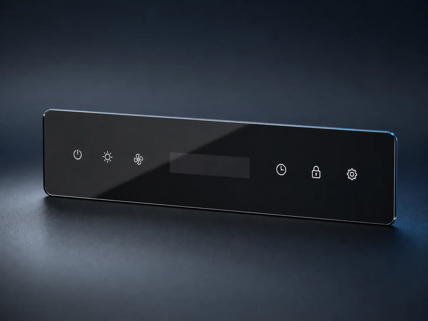
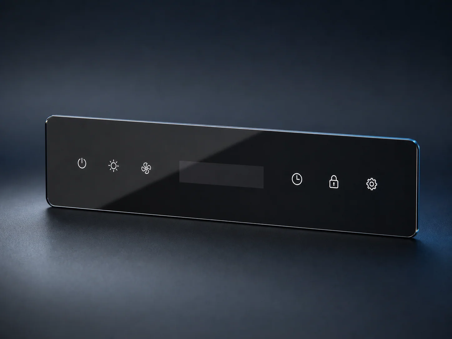

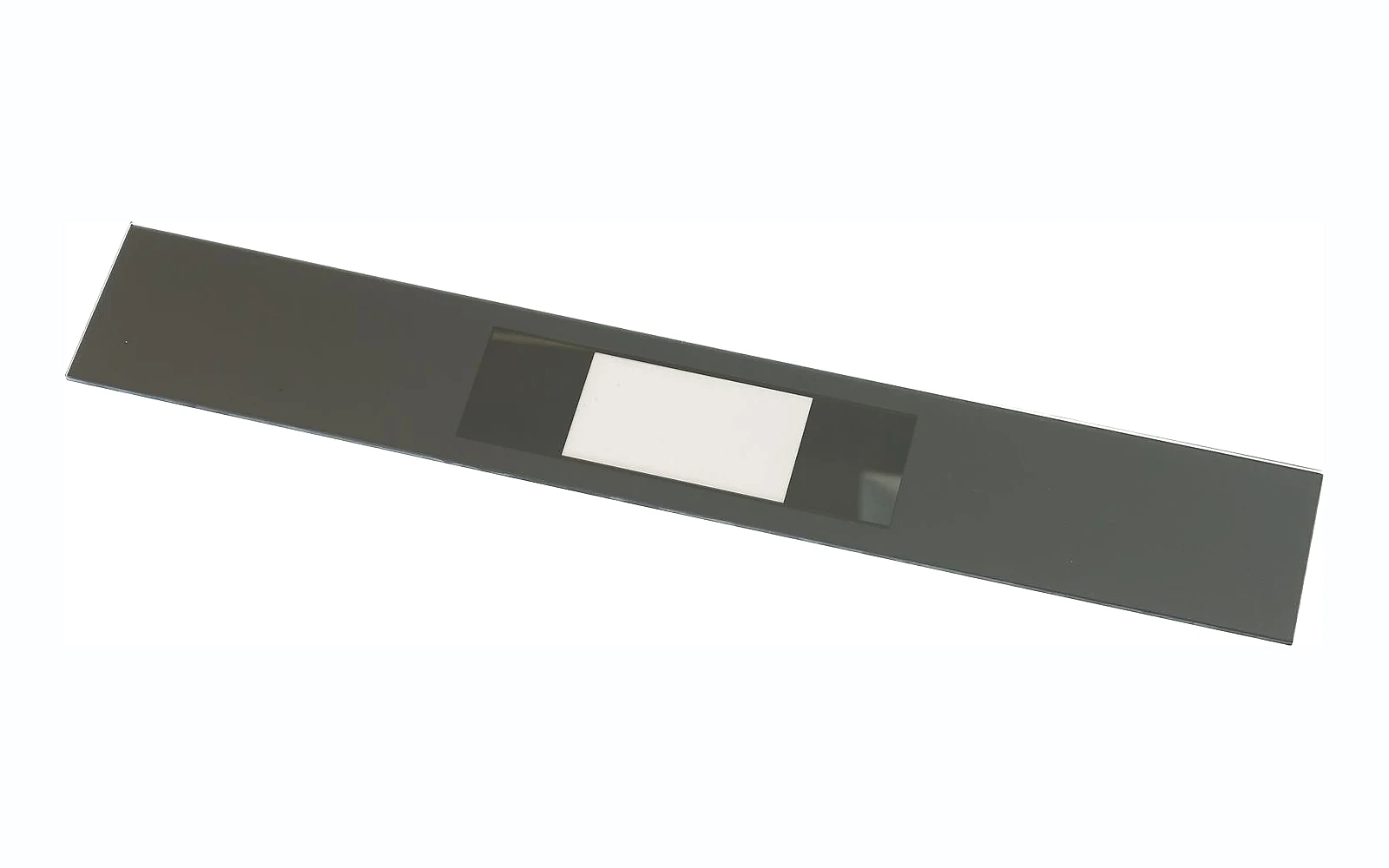

Dead-front appliance control panel glass creates a clean, dark surface when the appliance is off while allowing selected displays, icons or indicators to become visible when illuminated. The effect is often called “hidden-until-lit” or “shy-tech.” It can make an appliance look simpler and more premium, but it is not produced by choosing black glass alone.
The final appearance depends on an optical stack: glass substrate, printed layers, coating if used, transparent or semi-transparent windows, adhesive, air gap, display brightness, sensor position and the color of the backing structure. A change in any one layer can affect powered-off concealment, illuminated brightness, color and touch performance.
For an OEM project, the best specification separates what the user should see in each operating state from how the glass supplier will manufacture it. This guide gives product engineers, industrial designers and purchasing managers a practical framework for defining, sampling and sourcing the panel.
Quick answer: how should dead-front control panel glass be specified?
Specify the panel as a complete optical and mechanical interface. The RFQ should include:
- Appliance application and installation orientation.
- Base glass, nominal thickness and strengthening condition.
- Overall geometry, datums, holes, cut-outs, edge profile and tolerances.
- Powered-off color, gloss, reflection and concealment targets.
- Illuminated brightness, contrast, color, uniformity and viewing-angle targets.
- Controlled print artwork, layer sequence, opacity and display-window construction.
- Touch, proximity, infrared, RFID or other sensor locations and keep-out zones.
- Mounting, adhesive, gasket, frame and allowable assembly stress.
- Optical, dimensional, cosmetic, chemical and functional validation methods.
- Approved master samples, change control, shipment inspection and packaging.
Do not approve the glass only on a white table. Evaluate it with the intended display, electronics, backing material and ambient lighting in both powered-off and illuminated states.
1. Start with the user interface, not the ink color
Before selecting glass or printing, define the visible states of the appliance.
Powered off
Document what the user should see when the product is not operating:
- Uniform black, gray or another color.
- Hidden display window.
- Permanently visible logo or symbol.
- Controlled reflection or matte appearance.
- No visible adhesive, sensor, frame or display outline.
Standby
Some products show only a power symbol, clock or status indicator. Define which graphics remain visible and their acceptable brightness.
Active operation
List every illuminated symbol, numerical display, bar, warning and color. State which elements can operate simultaneously, because overlapping light can reveal window boundaries or cause cross-talk.
Service or failure state
Engineering may need additional diagnostic indicators that are not part of the normal user interface. Include them in the artwork and optical review rather than adding them after approval.
A simple state table is an effective control document. It aligns industrial design, electronics, software, glass printing and inspection teams around the same visual result.
2. Define the complete optical stack
Dead-front performance cannot be predicted from a glass sample viewed by itself. Describe the layers from the user side to the electronics:
- Front glass surface.
- Glass substrate.
- Printed decorative and masking layers.
- Optional coating.
- Optical adhesive, air gap or gasket.
- Display, light guide, LED or sensor.
- Internal frame or backing material.
Record the orientation of the printed and coated surfaces. Printing viewed through glass can have a different color and gloss from printing viewed directly. An air gap can increase internal reflection; an adhesive can change transmission and color.
SCHOTT’s smart guidance for home appliances describes hidden displays, backlit symbols and sensor integration as part of a coordinated human-machine interface. The same principle applies to an OEM RFQ: evaluate the panel as an interface stack rather than as isolated decorative glass.
3. Choose substrate and thickness around the assembly
Possible substrates include clear, low-iron, tinted or customer-specified glass. The correct choice depends on:
- Target powered-off color.
- Required display color neutrality.
- Panel size and unsupported span.
- Holes, slots and shaped edges.
- Mounting and impact exposure.
- Touch-sensor sensitivity.
- Strengthening and product-level validation.
Low-iron glass can reduce the green contribution of standard clear glass, which may matter for white icons or light colors. Tinted glass can assist concealment but may reduce transmitted brightness. Neither choice automatically creates a dead-front effect.
Thickness should be selected with the frame and support system. A thicker panel may change touch sensitivity, optical path, weight and edge appearance. A thinner panel may require different support or strengthening. Avoid specifying thickness only from a previous product photograph.
All geometry should be fabricated before tempering. Holes, slots, notches, shaped profiles and edge finishing need to be finalized early.
4. Translate visual intent into measurable optical targets
Words such as “deep black,” “premium” and “invisible display” are useful design goals but poor inspection criteria. Convert them into agreed comparisons or measurements.
Powered-off concealment
Define:
- Approved color master.
- Gloss or reflection target.
- Maximum visible contrast between the display window and surrounding mask.
- Inspection background and ambient light.
- Viewing distance and angle.
- Whether the display is physically installed during inspection.
Illuminated performance
Define:
- Minimum and maximum brightness at the user position.
- Color coordinates or approved color master where critical.
- Uniformity across each symbol or display window.
- Contrast against the surrounding black.
- Readability at specified viewing angles.
- Acceptable halo, light leakage and cross-talk.
Transmission
If numerical values are required, specify the wavelength range, instrument, sample orientation and measurement location. A general “50% transmission” requirement is incomplete when the display uses colored LEDs or a narrow optical band.
Use conditional language in early development. For example, “target transmission to be confirmed with production-intent display and adhesive” is more honest than a fixed number copied from an unrelated design.
5. Design print layers for masking and illumination
Silk-screen printing is commonly used for stable high-volume appliance graphics, borders and masking. Digital printing may be considered for complex color gradients, shorter runs or design variation. The right process depends on artwork, durability, volume and appearance requirements.
The controlled artwork should show:
- Glass outline and datums.
- Print side and viewing direction.
- Layer sequence.
- Color references.
- Opaque masks.
- Semi-transparent display windows.
- Icons and permanent graphics.
- Touch or sensor zones.
- Registration tolerances.
- No-print and adhesive keep-out areas.
Opaque masking
The mask should conceal the frame, adhesive and electronics under the defined inspection conditions. More ink is not always better: excessive build can affect surface flatness, adhesion or assembly. Agree on performance rather than an undocumented number of print passes.
Semi-transparent windows
A display window may use a controlled ink density, coating or combination of layers. The goal is to balance powered-off concealment with powered-on readability. Validate the window with the actual display, not only a light box.
Fine icons and text
Confirm minimum line width, gap and registration capability with the chosen print process. Very fine reversed text, closely spaced symbols and multiple colors may require design adjustment for repeatable production.
6. Integrate touch and sensor functions
Modern appliance control glass may sit in front of capacitive touch keys, sliders, proximity sensors, infrared receivers, cameras or RFID/NFC elements. Each technology interacts differently with glass, printing, coating and spacing.
For capacitive touch, engineering should review:
- Glass thickness and dielectric stack.
- Distance from sensor to user surface.
- Adhesive or air gap.
- Printed or conductive layers.
- Moisture and cleaning conditions.
- Grounding and nearby metal.
- Glove or wet-finger requirements.
For infrared or optical sensors, define the relevant wavelength and target transmission. A window that looks transparent to the eye may not have the required infrared behavior. For camera or ambient-light sensors, haze, reflection and angle may be critical.
The glass fabricator should manufacture the defined window and provide component measurements where agreed. The OEM should validate sensor performance in the complete electronics and enclosure assembly.
7. Control geometry, datums and registration
The panel drawing should include:
- Overall length, width and thickness.
- Corner radii and shaped profiles.
- Holes, slots and notches.
- Edge finish.
- Critical assembly datums.
- Display-window and icon positions.
- Registration tolerances.
- Flatness or bow limits only where functionally required.
Use shared datums for the glass, artwork, display and housing. If the display window is located from one edge while the electronics are located from another, accumulated variation can cause visible misalignment.
During DFM review, ask the supplier to identify:
- Fragile hole-to-edge distances.
- Difficult internal radii.
- Tolerance conflicts after grinding.
- Print features near curved edges.
- Need for dedicated positioning or inspection fixtures.
- Areas where the cosmetic expectation exceeds process capability.
Freeze the drawing and artwork revisions together. A print file without the matching part revision is a common source of expensive mistakes.
8. Design the mounting system around glass behavior
Dead-front control panels may be bonded, clipped, gasketed or mechanically retained. The mounting method affects optical appearance, touch sensitivity and stress.
During installation preparation, check:
- Support surfaces are flat and clean.
- Adhesive thickness and cure are controlled.
- Adhesive cannot become visible through the window.
- Gaskets do not create local distortion.
- Metal clips have compliant contact surfaces.
- Fasteners cannot directly contact the glass.
- The housing does not twist the panel.
- Cables and display modules do not push against the glass.
If the panel covers a large display area, also evaluate thermal expansion and heat from electronics. The correct solution belongs to the full assembly, not the glass drawing alone.
9. Build a validation matrix
A useful validation plan states what is checked, by whom, on which assembly revision and against which acceptance criterion.
Glass component inspection
Factory inspection may include:
- Dimensions and feature positions.
- Edge and corner condition.
- Print registration.
- Color comparison.
- Opacity and transmission.
- Coating or surface appearance.
- Cosmetic defects by zone.
- Traceability to batch and revision.
Optical validation
Use the intended display and assembly to evaluate:
- Powered-off concealment.
- Powered-on brightness and color.
- Viewing angle.
- Uniformity.
- Halo and light leakage.
- Ambient-light readability.
- Window visibility under direct reflection.
Functional validation
Depending on the product, evaluate:
- Touch sensitivity and false activation.
- Wet-finger or cleaning conditions.
- Sensor transmission.
- Temperature and humidity exposure.
- Chemical resistance.
- Abrasion and repeated cleaning.
- Impact and assembly loads.
- Electronics heat and thermal cycling.
Do not quote a generic test level unless it is confirmed by the OEM’s product requirements. Record the test fixture, electronics revision, software mode, adhesive, frame and glass orientation.
10. Establish appearance masters and change control
Instrument readings are useful, but many premium black-panel decisions still require a controlled physical reference.
Create:
- Approved color master.
- Powered-off assembled master.
- Powered-on visual reference.
- Boundary samples for acceptable and unacceptable defects.
- Approved artwork and print-layer file.
Store samples away from contamination and uncontrolled UV or temperature exposure. Record the approval date and revision. If ink, substrate, coating, display, adhesive or backing material changes, assess the effect on the optical stack before production continues.
For shipment inspection, verify the correct drawing and artwork revision, dimensions, appearance, labels and packaging. Random photographs can support the record but should not replace controlled inspection.
11. Plan samples and pilot production
DFM or engineering sample
Confirm geometry, edgework, assembly fit, print feasibility and basic display alignment.
Optical sample
Use production-intent glass, inks, coating, display and backing to approve both powered-off and illuminated states.
Functional sample
Validate touch, sensors, cleaning, environmental exposure and assembly behavior.
Pilot production
Use production-intent screens, fixtures, inspection conditions and packaging. Evaluate repeatability across the pilot batch before mass-production release.
This staged approach keeps a visual preference from being mistaken for complete product validation.
Dead-front control panel glass RFQ checklist
Include:
- Controlled 2D glass drawing.
- Housing or assembly cross-section.
- Vector artwork with print layers.
- Powered-off and powered-on state table.
- Color, gloss and concealment references.
- Display type, brightness and wavelength information.
- Touch or sensor technology and locations.
- Adhesive, gasket and backing material.
- Operating, cleaning and environmental conditions.
- Prototype and annual volume.
- Inspection, documentation, packaging and destination requirements.
Ask the supplier to return its DFM comments, proposed print route, optical assumptions, sample stages, inspection method and open questions.
FAQ
What does dead-front glass mean?
It describes a panel that conceals selected displays or symbols when they are off and reveals them when illuminated. The effect comes from the complete optical stack, not from black glass alone.
Can the glass supplier guarantee display brightness?
The supplier can manufacture and measure an agreed glass or printed window, but final brightness depends on the display, air gap or adhesive, backing, electronics and ambient light. Validate the complete assembly.
Is silk-screen printing suitable for touch controls?
It is commonly used for appliance control panels, but the print stack, glass thickness, sensor construction and mounting must be evaluated together. The OEM should validate touch performance in the intended assembly.
How should black color be approved?
Use a controlled physical master or agreed color measurement together with defined lighting, background, viewing distance and assembly condition. Evaluate both powered-off and illuminated states.
Which files are required for quotation?
A dimensioned drawing, vector artwork, UI state table, display and sensor information, mounting details, validation requirements, expected volume and destination provide a strong starting point.
Conclusion
Dead-front appliance control panel glass is an engineered user interface. A reliable program begins with visible-state requirements and a documented optical stack, then connects them to glass geometry, printing, sensors, mounting and validation.
The supplier should control manufacturing and component inspection. The OEM should validate the display, touch system and complete appliance. Approved masters, staged samples and disciplined revision control provide the bridge between an attractive prototype and stable repeat production.
CTA: Review your control panel glass design
Send Tairong your drawing, vector artwork, powered-off and illuminated targets, display or sensor information and expected volume. Our team can review the manufacturing information needed for sampling and quotation.
Primary CTA: Ask an Engineer
Related products: Custom appliance control panel glass
Related guide: Silk-screen vs. digital printing for appliance glass