
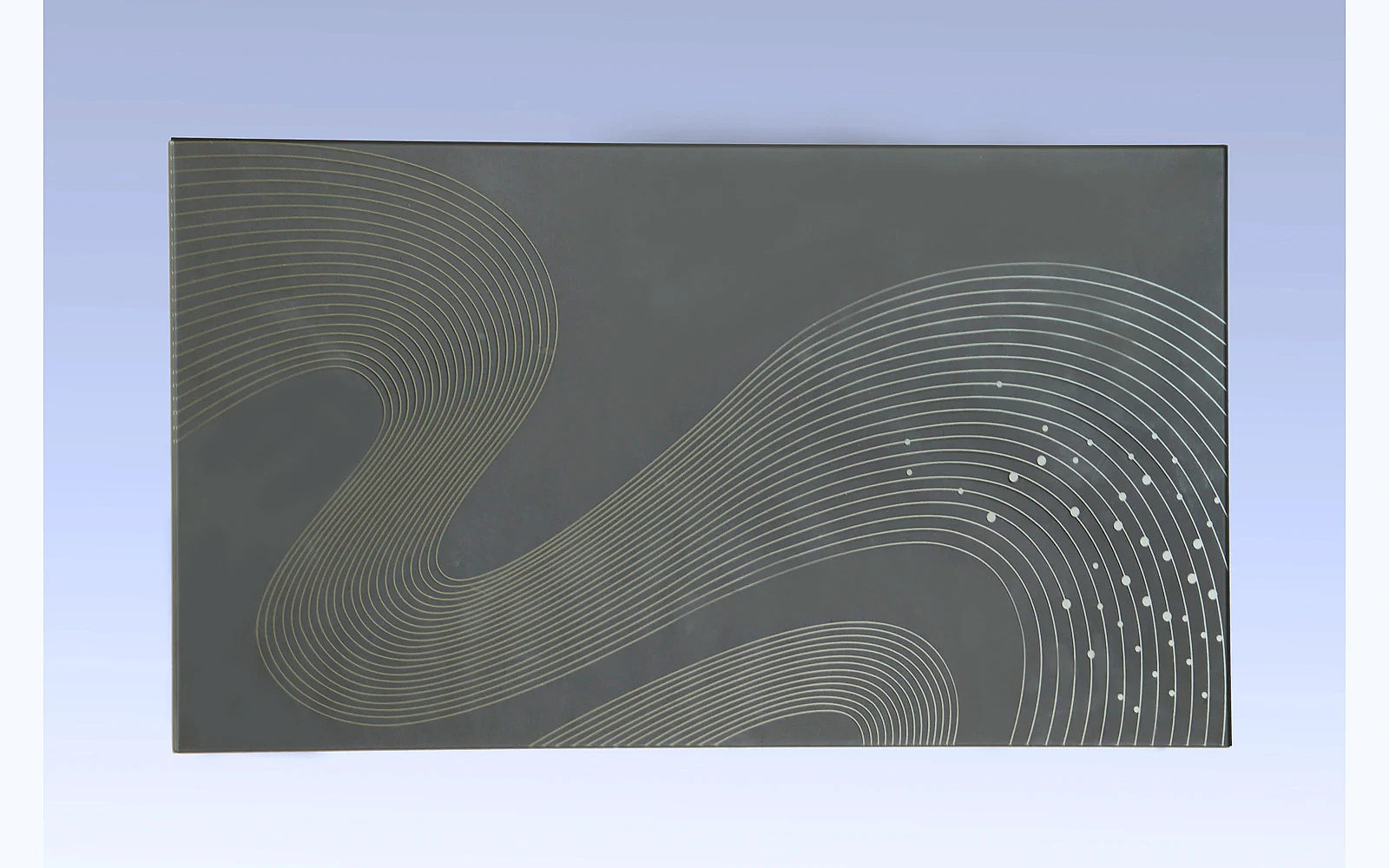

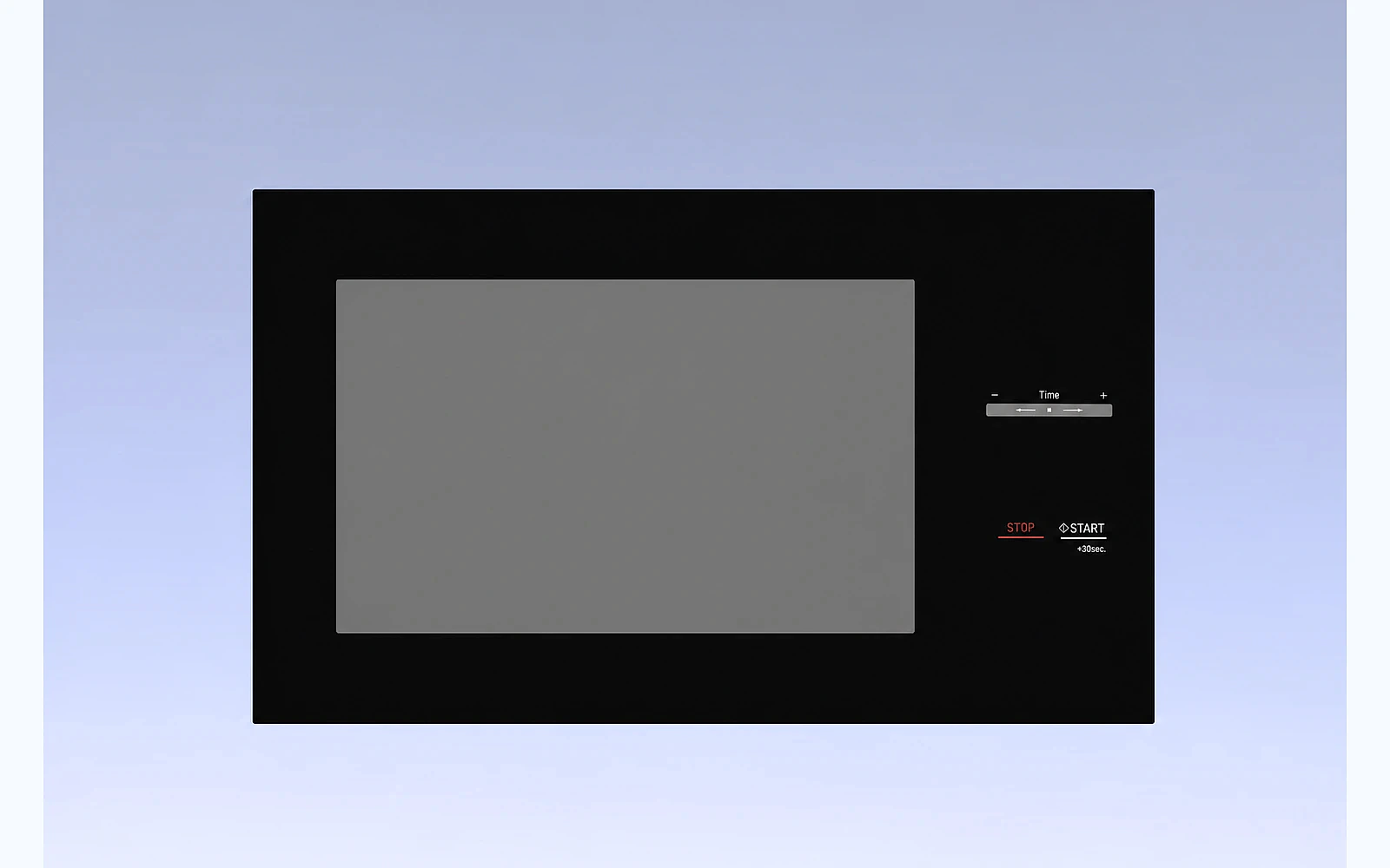
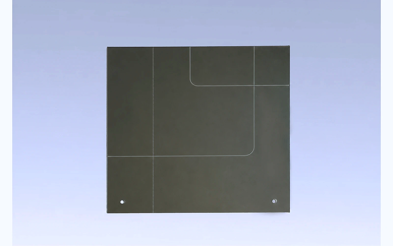

Coated appliance glass can hide a display, create a mirror-like appearance, improve optical readability, provide an electrically conductive layer or change how a customer cleans and touches the surface. These are different functions and they should not be specified with one vague request for "coated glass."
For an OEM program, the correct coating depends on the complete optical and mechanical stack: base glass, print layers, display, adhesive, air gap, touch sensor, backing material, lighting and cleaning environment. A coating that looks attractive as a loose sample may behave differently after it is printed, bonded or installed in the appliance.
This guide helps product engineers, industrial designers and purchasing teams define the required function, select a realistic coating route and build a measurable qualification plan.
Quick answer: how should an OEM specify coated appliance glass?
Start with the result the appliance must achieve. Then define:
- The component and coated-surface position.
- Powered-off and powered-on appearance.
- Optical targets such as transmission, reflection, color and haze.
- Electrical target and contact design for conductive coatings.
- Printed areas, windows, masks and coating exclusions.
- Adhesive, touch, display and backing-material stack.
- Chemical, abrasion, humidity and temperature exposure.
- Measurement equipment, points and acceptance range.
- Approved master samples and cosmetic inspection conditions.
- Prototype, pilot and change-control requirements.
Use measurable targets rather than a trade name alone. "Mirror coating," "anti-glare" and "anti-fingerprint" can describe different constructions and performance levels from different suppliers.
1. Define the function before choosing the coating
Ask what problem the surface must solve.
Decorative or mirror appearance
A reflective surface can create a premium powered-off look and help conceal components behind the glass. The design needs to balance reflection with the transmission required for illuminated information.
Hidden display
A dead-front display should be difficult to see when off, but bright, uniform and correctly colored when on. This function may depend on a combination of glass tint, printing, coating, display brightness and the air gap.
Electrical conductivity
A transparent conductive coating may be used when the project requires an electrical function. The specification must include sheet resistance, active area, contact position and the intended circuit. "Conductive glass" without an electrical drawing is not enough for quotation or validation.
Reduced reflection or glare
Anti-reflective and anti-glare are not synonyms. An anti-reflective approach aims to reduce reflected light, while an anti-glare surface typically diffuses reflected images. Diffusion can also affect display sharpness and haze, so the selection must be validated with the actual user interface.
Easy-clean or anti-fingerprint behavior
An easy-clean surface may reduce surface energy and make fingerprints easier to remove. It does not make the glass maintenance-free. The OEM still needs a controlled cleaning method and durability acceptance after repeated wiping.
One panel may need more than one function, but each function adds compatibility and validation questions. Prioritize the customer requirement instead of adding coatings as an undifferentiated feature list.
2. Specify the full optical stack
The glass is only one layer between the customer and the display or internal component. Document the stack in viewing order:
- User-facing surface treatment.
- Base glass and thickness.
- Decorative or masking print.
- Functional coating.
- Optical adhesive or air gap.
- Touch sensor.
- Display or indicator.
- Rear mask, housing or backing.
Identify the numbered glass surface that receives each print or coating. This prevents mistakes when a drawing is mirrored or the part is evaluated from the wrong side.
Evaluate both powered-off and powered-on states
For display glass, define:
- Maximum visibility of internal components when off.
- Minimum readable brightness when on.
- Color shift through the glass.
- Uniformity across the window.
- Reflected image or glare under expected ambient lighting.
- Acceptable viewing angle.
- Light leakage around printed masks.
Photographs help communicate intent but are not a complete optical specification. Camera exposure, white balance and display settings can hide differences that a user will see.
3. Turn appearance language into optical targets
Common measurable properties include:
- Visible-light transmission.
- Reflectance from the viewing side.
- Haze.
- Color coordinates or color difference.
- Gloss.
- Spectral transmission where display color is critical.
The relevant target and measurement geometry depend on the coating. State the instrument, aperture, measurement side, background and number of points where necessary.
Pilkington's technical information for a mirror-coated glass product is a useful example of why orientation, reflection, transmission and handling belong in the product discussion. An appliance project still needs targets developed for its own stack and use conditions.
Use a physical master for complex appearance
Numbers do not always capture texture, visual density and the relationship between a display window and printed border. Approve a signed master sample under defined lighting, then retain boundary samples for acceptable variation where appropriate.
The master should identify:
- Part number and revision.
- Coating and print orientation.
- Approval date.
- Viewing side.
- Inspection lighting and background.
- Display and backing configuration used for approval.
4. Define conductive coatings electrically
If the coating has an electrical function, include:
- Target sheet resistance and tolerance.
- Measurement method and points.
- Conductive area and isolation pattern.
- Busbar or electrical contact design.
- Contact material and pressure.
- Areas that must be masked.
- Maximum permitted visual nonuniformity.
- Environmental and aging requirements.
Sheet resistance measured on a flat coupon does not prove performance after patterning, printing, bonding and assembly. Validate the complete circuit and thermal behavior.
Coordinate the electrical and mechanical drawings
A contact pad may compete with an adhesive bead, printed border or cosmetic zone. Review all layers together so that:
- The contact can be assembled repeatably.
- The coating is not scratched by hardware.
- Adhesive does not contaminate the contact area.
- Electrical isolation distances are maintained.
- Inspection probes can reach the measurement points.
Any coating removal or laser-patterned feature should be dimensioned from controlled datums.
5. Plan printing and coating sequence together
Decorative printing can mask the frame, carry icons and create display windows. Its interaction with the coating depends on:
- Which layer is applied first.
- Process temperature.
- Ink chemistry.
- Adhesion to the glass or coating.
- Required opacity.
- Electrical continuity.
- Optical appearance through the substrate.
Do not release print artwork independently from the coating specification. A change in ink density can change powered-off concealment and powered-on brightness even if the coating itself is unchanged.
The process route should identify:
- Cutting, drilling and edge finishing.
- Cleaning.
- Tempering or other strengthening process.
- Coating and any patterning.
- Printing and curing.
- Inspection.
- Protective film and packaging.
The exact order depends on the selected materials and process. The supplier should confirm compatibility before samples are made.
6. Design coating exclusions and edge zones
A coated panel may need clear areas for:
- Adhesive bonding.
- Electrical isolation.
- Grounding or contact.
- Optical windows.
- Printed icons.
- Seals or gaskets.
- Inspection marks.
Dimension these areas and define the acceptable transition boundary. The design should also address coating behavior at the glass edge, holes and notches.
If an adhesive bonds to the coated side, qualify adhesion to the actual coating rather than relying on glass-only data. Cleaning, primer and cure conditions must reflect the production process.
7. Build a durability plan around customer use
The coating may encounter:
- Finger contact.
- Household cleaners.
- Detergent or cooking residue.
- Humidity.
- Elevated temperature.
- Thermal cycling.
- Abrasive cloths or particles.
- Adhesive and gasket chemicals.
- Protective film.
- Packaging contact.
A useful test specifies the exposure and acceptance criteria. For example, "cleaning resistance" should identify the cleaner, concentration, wiping material, applied load, number of cycles and permitted change in optical or cosmetic properties.
Depending on the application, the validation plan may include:
- Coating adhesion.
- Abrasion or wipe cycling.
- Chemical spot tests.
- Humidity exposure.
- Temperature cycling.
- Optical measurement before and after exposure.
- Electrical resistance before and after aging.
- Bond-strength testing.
- Cosmetic inspection after packaging simulation.
Do not imply that one laboratory result covers every appliance. The relevant conditions for an oven control panel, refrigerator display and charging interface can be different.
8. Align cosmetic inspection with coating behavior
Coatings can make dust, pinholes, scratches, color variation or handling marks more visible. Establish:
- Critical and noncritical viewing zones.
- Inspection lighting.
- Background.
- Viewing distance and angle.
- Inspection time.
- Powered-on or backlit inspection where applicable.
- Limits for scratches, pinholes, stains and nonuniformity.
Inspect from the normal customer side. Also include process-side inspection for defects that may affect bonding, conductivity or durability even if they are hidden after assembly.
Factory testing should record the part number, revision, coating batch, measurement method and results. Where the coating is functional, the final inspection plan should include the critical optical or electrical characteristic rather than only a visual check.
9. Use staged samples to reduce uncertainty
Optical feasibility sample
Compare a small number of coating and printing combinations with the actual display and backing. Eliminate options that cannot meet the powered-off and powered-on balance.
Engineering sample
Confirm geometry, coating exclusions, electrical contacts, bonding and assembly fit.
Appearance master
Approve the final surface, color, reflection and display appearance under controlled conditions.
Functional validation sample
Complete chemical, abrasion, environmental, electrical and assembly tests using production-intent materials.
Pilot production
Verify repeatability, measurement capability, handling, protective film and export packaging before release.
This sequence is more reliable than approving a beautiful loose sample first and discovering later that it is difficult to bond, touch through or measure consistently.
10. Qualify the supplier's coating control
Ask the manufacturer how it controls:
- Incoming glass and coating materials.
- Surface cleaning before coating.
- Coating thickness or functional proxy.
- Patterning and mask position.
- Optical and electrical measurement.
- Printing compatibility.
- Handling between processes.
- Revision and recipe control.
- Nonconforming product.
- Protective film and packing.
For outsourced coating steps, clarify responsibility for traceability, inspection and corrective action. The appliance buyer should have one controlled product specification and a clear owner for shipment release.
Shipment inspection should verify coating orientation, approved revision, quantity, cosmetic status, functional results where required, labels and packaging condition.
Coated appliance glass RFQ checklist
Provide:
- Controlled glass drawing.
- Application and component position.
- Full optical and mechanical stack.
- Coating function and preferred surface.
- Optical targets and measurement method.
- Electrical targets and contact design, if applicable.
- Print artwork and color reference.
- Coating exclusions and critical zones.
- Adhesive, touch and display details.
- Cleaning, environmental and durability conditions.
- Prototype quantity and production forecast.
- Destination and packaging requirement.
Ask the supplier to return:
- Recommended coating construction.
- DFM and compatibility comments.
- Proposed process sequence.
- Measurement and inspection plan.
- Sample stages.
- Known limitations and quotation assumptions.
FAQ
What is coated appliance glass?
It is appliance glass with a deposited or surface-applied layer that changes optical, electrical, decorative or cleanability performance. The required construction depends on the appliance and should be defined by measurable function.
Is mirror-coated glass suitable for a hidden display?
It can contribute to a hidden-display appearance, but suitability depends on transmission, reflection, display brightness, printing and the complete optical stack. Evaluate it with the actual display in both off and illuminated states.
What is the difference between anti-reflective and anti-glare glass?
Anti-reflective treatment aims to reduce reflected light. Anti-glare treatment typically diffuses reflections, which can also affect haze and display sharpness. The correct choice depends on the viewing environment and user-interface requirement.
Can printing be applied to coated glass?
Potentially, but the ink, coating, curing process, layer order and adhesion must be compatible. Approve the combined construction rather than qualifying the print and coating separately.
How should a conductive coating be specified?
Define sheet resistance, tolerance, measurement points, active pattern, electrical contacts, masked areas and environmental tests. Validate the complete electrical and mechanical assembly.
Why is an approved master still needed when optical data are available?
Measured values control important characteristics, but a master sample can capture the overall relationship among reflection, color, print density, display windows and backing materials under agreed viewing conditions.
Conclusion
The best coating is the one that solves a defined appliance requirement and remains compatible with printing, bonding, touch, display and customer cleaning.
Begin with the powered-off and powered-on experience. Map the full layer stack, set measurable optical or electrical targets, define coating exclusions and validate the production-intent assembly. Then use master samples, inspection data and pilot production to control repeatability.
This approach gives OEM teams a defensible material decision and gives suppliers enough information to propose a realistic manufacturing route.
CTA: Discuss a coated appliance glass application
Planning a mirror display, conductive surface, printed control panel or decorative coated glass part? Send Tairong your drawing, optical stack, target function, artwork and validation conditions for a manufacturing review.
Primary CTA: Ask for Product Catalog
Related products: Custom coated glass solutions
Related application: Custom control panel glass