


Quick answer: what should an appliance display-window specification include?
An effective display-window specification defines the finished optical stack, not only the glass color. At minimum, it should identify the active viewing area, visible-light transmission target, haze limit, transmitted or reflected color target, powered-off masking requirement, measurement geometry, illuminant, backing condition and acceptance method. The values must then be verified with the production-intent display, adhesive, air gap, enclosure and ambient lighting. A dark window that looks elegant on a loose sample can make a display unreadable after assembly; a highly transparent window can expose electronics when the appliance is off.
For an OEM buyer, the most important rule is simple: specify what the customer must see in both the powered-on and powered-off states, then connect that appearance to measurable optical criteria and a signed physical master.
Why display windows are more difficult than they appear
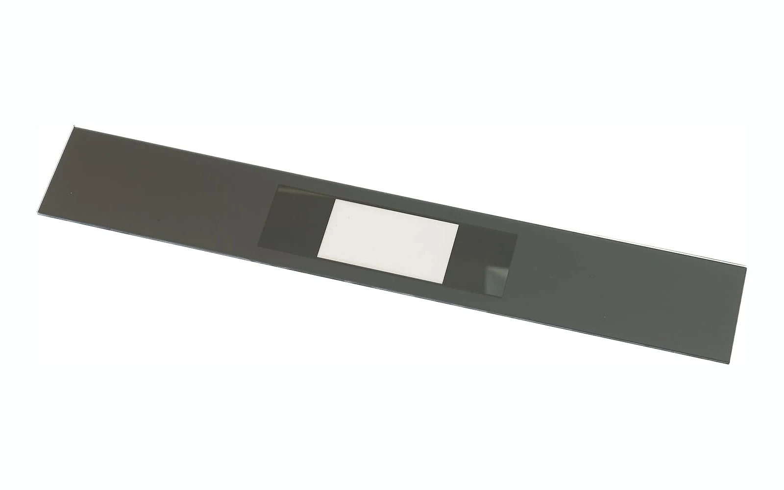
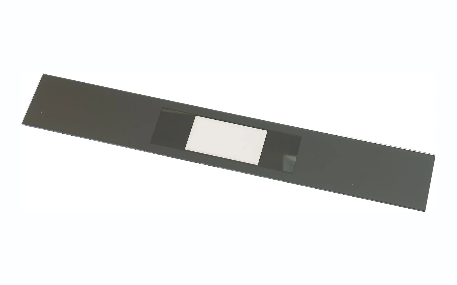
A control-panel window is often a small area within a larger printed or coated glass fascia. It may cover an LED segment display, LCD, indicator array or touch interface. The window therefore has two jobs that can conflict:
- transmit enough useful light for clear information;
- conceal the display module, adhesive, wiring and housing when inactive.
The final result depends on the complete product application. Glass thickness, body tint, ceramic ink, coating, dot pattern, display luminance, air gap, adhesive, black backing and ambient light all affect the perceived result. Even the observer angle and distance can change whether the window appears uniform.
This is why a request such as “make the window 30% transparent” is incomplete. It does not identify the wavelength range, measurement equipment, reference method, tolerance, viewing angle or whether the result applies to bare glass or the assembled appliance.
The optical terms an engineering team should control
Visible-light transmission
Luminous transmittance describes how much visible light passes through a specimen under a defined measurement method. It is useful for comparing candidate window constructions, but it is not the same as display readability. Two samples with similar integrated transmission can render a blue, red or white display differently because their spectral transmission curves differ.
For a color display or narrow-band LED, request spectral transmission data across the relevant wavelength range when color shift or brightness loss is critical. For a simple indicator, a production-intent illuminated mock-up may be the most practical verification method.
Haze and image clarity
Haze describes forward scattering that can make displayed symbols appear cloudy or reduce contrast. Measurement concepts such as those in ASTM D1003 are widely recognized, but the cited method was developed for transparent materials and must not be treated as an automatic appliance-glass compliance requirement. The buyer and supplier should agree whether the method is appropriate for the actual glass, ink or coating stack, including specimen support and instrument configuration.
A low haze number alone does not guarantee a sharp display. Surface texture, printing dots, coating non-uniformity and the distance between glass and display can also blur the image. If icon edge definition matters, add a visual or camera-based contrast check on an assembled sample.
Transmitted and reflected color
Color should be stated with a color system and test condition rather than a descriptive word such as “smoke black.” ISO/CIE 11664-4 defines the CIELAB color space, while ISO/CIE 11664-6 defines the CIEDE2000 color-difference formula. These frameworks can support a repeatable agreement, provided that the illuminant, observer, instrument geometry, backing and measurement mode are also defined.
ISO/CIE 11664-2 defines standard illuminants including A, D65 and D50. The appropriate illuminant depends on the intended evaluation. A D65-based appearance check may represent daylight-like conditions, while an appliance installed under warm indoor lighting may require an additional visual assessment.
Powered-off opacity and dead-front performance
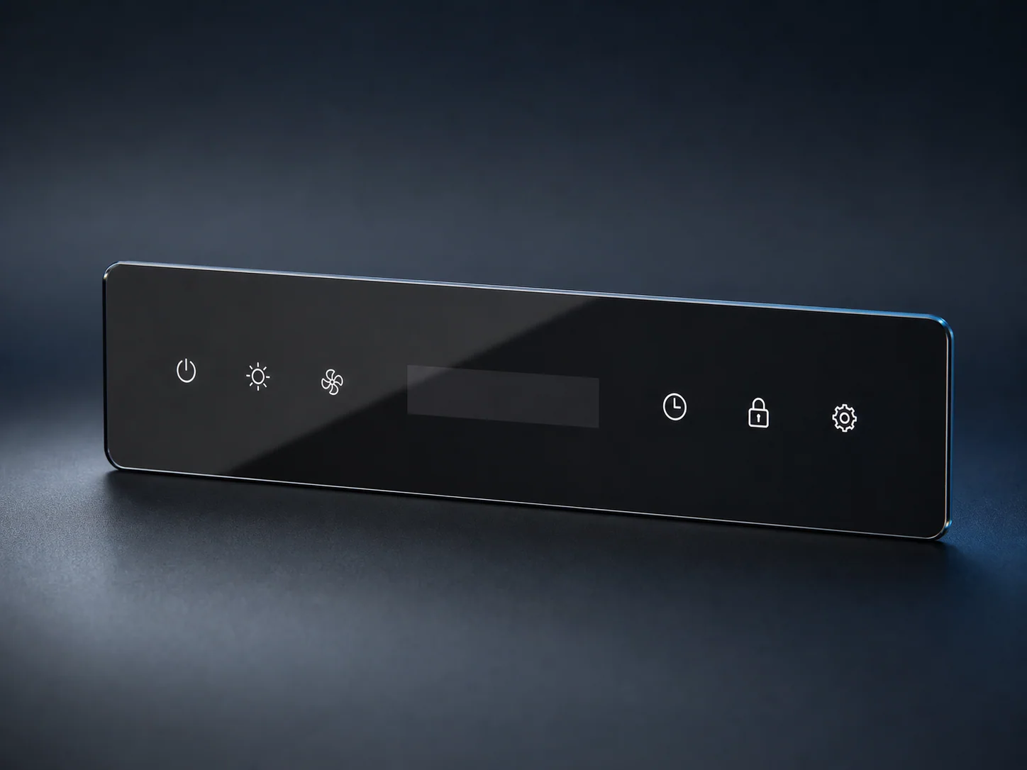
For a dead-front design, the inactive display should visually merge with the surrounding black area. This depends on reflected color, gloss, transmission, internal reflections and the module behind the window. A bare glass coupon on a white table is therefore a poor approval setup.
Define the off-state test with the intended black backing or display module installed. Agree the ambient illuminance, viewing distance and angle. If the window must remain hidden from oblique directions, include those angles in the approval protocol.
Gloss, reflection and surface uniformity
Reflections can reduce display contrast and reveal differences between the window and the surrounding print. A mirror-like surface may be desirable for premium styling but difficult to read near a bright window. An anti-glare or textured surface may improve readability but change black depth and image sharpness.
Object-color measurement practices such as ASTM E1164 help define spectrometric data collection, yet the measurement arrangement still has to match the product question. Record whether specular reflection is included or excluded and whether the reading is taken from the glass side or print side.
A practical specification table for an RFQ
The table below is a framework, not a set of universal target values. The correct limits depend on the display, industrial design and user environment.
| Item | What the OEM should define | Why it matters |
|---|---|---|
| Window geometry | Active area, border, corner radii and positional datums | Prevents clipping and misalignment |
| Transmission | Target, tolerance, wavelength or luminous method | Controls display brightness loss |
| Haze or clarity | Method, limit and specimen condition | Controls cloudiness and symbol definition |
| Color | L*, a*, b* or spectral target; illuminant and observer | Controls black match and display color shift |
| Off-state masking | Backing, ambient light, distance and viewing angles | Controls dead-front concealment |
| On-state readability | Display module, drive setting, content and ambient light | Confirms actual user visibility |
| Surface finish | Gloss or texture zone and measurement side | Controls reflections and tactile appearance |
| Uniformity | Measurement points or visual zones | Detects print or coating variation |
| Appearance master | Approved physical sample and revision | Resolves qualities not captured by numbers |
Do not place every dimension and optical criterion on an uncontrolled email. Link the glass drawing, artwork, optical specification, display settings and appearance master to one product revision.
Step-by-step development workflow
1. Define the display and user environment
Before requesting glass samples, provide the display technology, emitting colors, typical and minimum luminance settings, active area, viewing distance and required angles. Identify whether the appliance is used in a bright kitchen, a laundry area, a commercial environment or another lighting condition.
The customer requirements should distinguish normal operation from special conditions. Direct sunlight, polarized eyewear, steam, condensation or cleaning residue can create separate risks that require system-level validation.
2. Build an optical stack drawing
Document the order and nominal spacing of glass, ink or coating, adhesive, air gap, display lens and backing. Mark which surface faces the user. This avoids a common problem: the sample is measured in one orientation but assembled in another.
If capacitive touch is integrated, include electrode position and adhesive thickness. The optical design must not be optimized independently from the touch stack. See our guide to capacitive touch through glass for the electrical and assembly interactions.
3. Screen candidate constructions with measurable data
Use small samples to compare printing density, coating, transmission and color before cutting production-size panels. Record the sample ID, recipe revision, glass lot where relevant, instrument, calibration status and measurement points.
Factory testing at this stage is a comparison tool. It helps narrow the design window, but it does not replace approval of the full-size, production-intent component.
4. Evaluate powered-off and powered-on assemblies
Mount the glass over the intended display and enclosure. Use fixed camera exposure or a controlled visual booth for comparison. Evaluate:
- display readability at defined brightness settings;
- black match between the window and surrounding print;
- leakage around the active area;
- visible adhesive, ribs, LEDs or electronics;
- color shift between display zones;
- readability at required viewing angles;
- reflections under representative ambient lighting.
Installation preparation matters. Temporary tape, an incorrect air gap or a white prototype housing can produce a misleading result. Replicate the intended bond line, backing color and mechanical support as closely as possible.
5. Freeze an approval package
The approval package should include the released drawing, artwork, optical targets, test method, instrument settings, display drive condition, visual inspection setup and signed sample. Define which criterion controls if the numerical result and visual master disagree.
6. Transfer the requirement to production control
For repeat production, identify which checks are performed per batch and which are periodic verification. A practical control plan may combine:
- first-article dimensional and artwork checks;
- transmission or color measurements at agreed points;
- visual comparison to the master under controlled lighting;
- powered display checks using a dedicated fixture when justified;
- revision and traceability records;
- shipment inspection for labels, surface protection and correct part identity.
The control frequency should reflect process risk and customer requirements rather than a generic template.
Common specification mistakes and how to prevent them
Approving only a digital rendering
Renderings communicate styling but cannot predict transmission, gloss or internal reflection. Approve physical samples with the intended display.
Using only an ink code or color name
Ink identity does not define the result after firing on a particular glass. Specify the finished appearance and measurable range.
Measuring bare glass but approving the assembled effect
If the requirement concerns the appliance, test the appliance stack. Bare-component data should support, not replace, system validation.
Ignoring measurement direction
Printed and coated constructions may show different values depending on which side faces the instrument. State the incident side and orientation.
Setting a narrow tolerance without capability evidence
An unnecessarily tight range can increase sorting and cost without improving user experience. Use prototype data and supplier capability review to set a functional tolerance.
Treating one number as a complete optical specification
Transmission, haze, color and off-state masking answer different questions. Combine metrics with an assembled visual test.
How procurement can compare supplier proposals
When reviewing quotations for custom control-panel glass, ask each supplier to state:
- whether quoted optics apply to bare glass or finished printed glass;
- the proposed measurement method and equipment class;
- the number and position of measurement points;
- how display windows are aligned to mechanical datums;
- how visual masters are stored and replaced;
- which variables are checked during factory testing;
- how nonconforming optical results are segregated;
- whether an assembled display fixture is needed for shipment release.
A credible answer explains controls and limitations. It should not promise perfect visual matching under every light source.
FAQ
What transmission value is best for a black appliance display window?
There is no universal best value. The correct target balances display luminance, off-state concealment, color, viewing angle and ambient light. Develop it using the actual display and enclosure, then define a measurable production range.
Can a supplier match a display window from a photograph?
A photograph can communicate intent but is not a sufficient optical standard because camera exposure, white balance and screen rendering change the appearance. Supply a physical master, display settings and measurable targets.
Should haze be specified for every control-panel window?
Specify it when scattering or image sharpness is functionally important. For some simple indicators, an assembled readability test may be more useful. The chosen method and limit must be agreed for the actual material stack.
How should a dead-front window be inspected?
Inspect it in powered-off and powered-on states with defined backing, ambient lighting, viewing distance and angles. Use both measurable optical checks and an approved physical appearance master.
Does the glass supplier approve final display readability?
The glass supplier can control component properties, but the appliance OEM should validate final readability because the display, drive electronics, adhesive, air gap, housing and ambient environment affect the result.
What files should accompany an optical-window RFQ?
Provide the dimensioned glass drawing, print artwork, optical-zone map, display information, target metrics, visual inspection conditions, intended stack and expected validation plan. Our drawing and DFM guide explains how to connect these files.
Conclusion
An appliance display window is an engineered optical interface, not simply a transparent rectangle. A robust specification links measurable transmission, haze and color to powered-off masking and powered-on readability on the real assembly. It also defines the test setup, viewing conditions, revision and physical master. That approach gives engineering, purchasing and the glass manufacturer a shared basis for prototype approval and repeat production.
Send your display-window requirements
Tairong manufactures custom appliance glass panels with CNC processing, edge finishing, tempering, silk-screen printing and optional coating according to approved project requirements. To review a display-window project, send your drawing, artwork, display type and target appearance. We will identify the information needed for sampling and a production-oriented DFM review without inventing unsupported optical claims.