
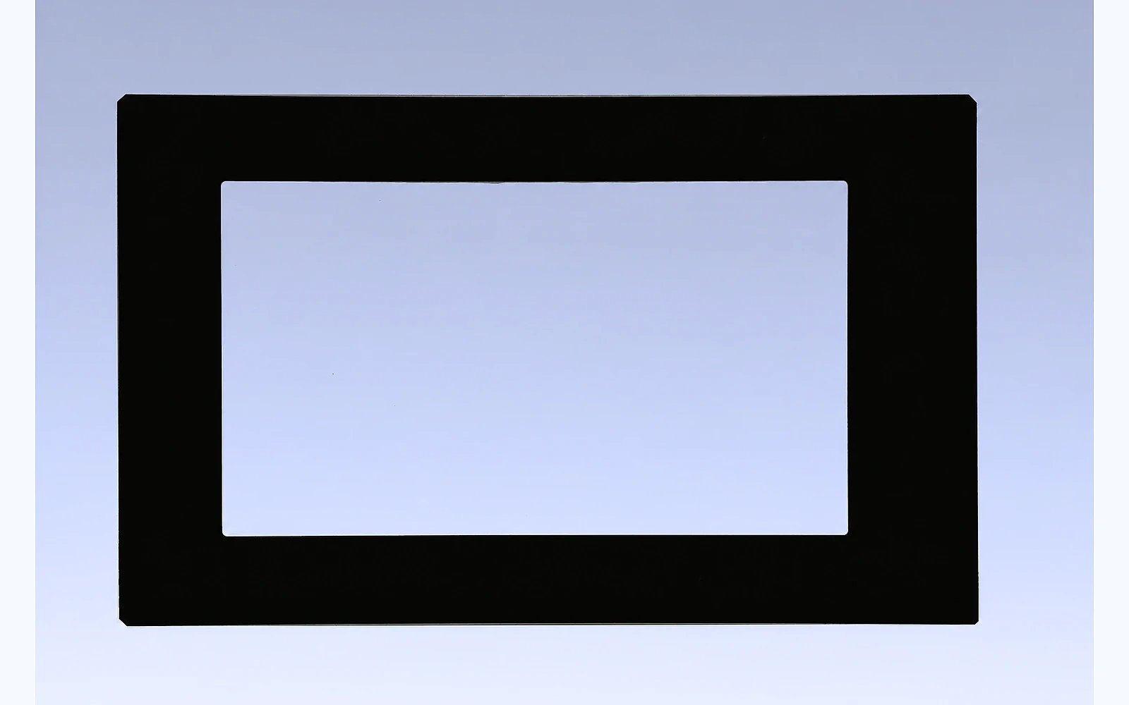

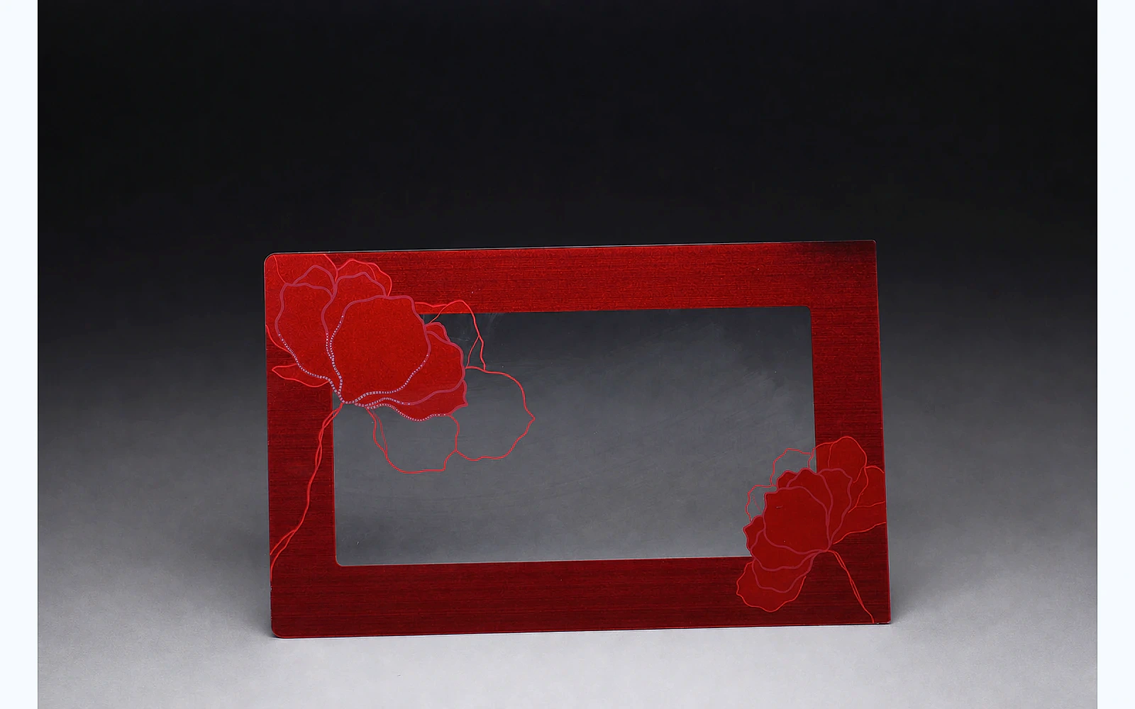


Microwave oven door glass should be sourced as part of a controlled door system, not as a generic black rectangle. The visible glass may provide the decorative surface, printed masking, a viewing window and alignment features, while the complete door assembly manages shielding, structural support, latching and user protection.
That distinction is important. A glass fabricator can manufacture the specified substrate, edgework, printing and coating, but microwave containment is a function of the complete appliance design. The metal screen, choke structure, frame, seals, hinges, latches and installation condition all influence the finished result. A supplier should therefore avoid claiming that one glass layer alone makes a microwave oven safe.
For procurement teams, the practical goal is to create an RFQ that lets manufacturers quote the same controlled part. For engineers, the goal is to connect the drawing and artwork with the door stack, display behavior, assembly interfaces and appliance-level validation. This guide explains how to do both.
Quick answer: what should an OEM specify for microwave oven door glass?
An OEM microwave oven door glass specification should define:
- The location and function of the glass in the complete door assembly.
- Base glass type, nominal thickness and strengthening condition.
- Overall dimensions, corner radii, holes, cut-outs, datums and tolerances.
- Edge finish and separate acceptance zones for exposed and hidden edges.
- Printed border, viewing window, dot pattern, icons and controlled artwork revision.
- Coating or optical targets, including transmission and powered-off appearance where relevant.
- Alignment to the metal screen, display, frame, handle and latching system.
- Mounting method, gasket, adhesive, clips and allowable assembly loads.
- Dimensional, optical, cosmetic, thermal, chemical and mechanical validation.
- Complete-appliance microwave leakage testing by the OEM or a qualified laboratory.
- Prototype stages, approved samples, shipment inspection and export packaging.
The drawing, artwork and validation plan should be the controlling documents. Photographs and old samples are useful references, but they do not replace measurable requirements.
1. Define the glass function within the door stack
A microwave door can contain several different layers. Before requesting a quotation, provide a simple cross-section and identify the layer being sourced.
Decorative outer glass
The external glass is the user-facing surface. It commonly carries a dark printed border, a transparent viewing area, decorative color, icons or a display window. Its appearance, cleanability and fit with the frame are usually critical.
Inner glass or transparent protective layer
An internal transparent layer can protect other door components or create a cleanable surface. Its thermal and cleaning exposure may differ from the outer panel. Do not assume that both positions need the same substrate, printing or edge treatment.
Screen and shielding components
Many microwave doors use a perforated metal screen or another engineered shielding construction behind the viewing area. The screen pattern, electrical continuity and choke system belong to the appliance design. If the sourcing drawing shows only the decorative glass, include a reference to the screen position so the supplier can control visual alignment without taking responsibility for an undefined shielding system.
The current edition of the applicable appliance safety standard should be determined by the OEM for each market. IEC 60335-2-25 addresses particular safety requirements for microwave ovens, including combination microwave ovens. Compliance is evaluated at appliance level, not inferred from the appearance of a glass panel.
2. Select the substrate and strengthening condition
The phrase “tempered microwave glass” is not a complete material specification. State the base substrate, thickness and required strengthening condition.
Typical project discussions may include:
- Clear soda-lime glass for printed decorative fronts.
- Low-iron glass when color neutrality through the panel is important.
- Tinted glass when the substrate contributes to the dark powered-off appearance.
- Another substrate when the product architecture, temperature exposure or validation plan requires it.
The correct choice depends on more than a headline strength or temperature value. Finished performance is affected by panel size, thickness, edge quality, holes, printing, coating, mounting stress, impact exposure and temperature gradients.
All cutting, drilling, slotting and edge processing should be completed before full tempering. Finalize the geometry before releasing tempering tooling or print screens. Changes after tempering generally require a new part.
Avoid copying thickness from another appliance
A previous microwave model may be a useful reference, but it does not prove that the same thickness is suitable for a new door. Compare:
- Unsupported span.
- Frame stiffness.
- Handle and hinge arrangement.
- Impact exposure.
- Assembly loads.
- Temperature profile.
- Required product-level tests.
Ask the glass supplier for manufacturability feedback, then validate the selected construction in the actual door assembly.
3. Control geometry from functional datums
An OEM drawing should define the geometry needed for both fabrication and final assembly:
- Overall length and width.
- Nominal thickness.
- Corner radii and shaped profiles.
- Holes, slots and notches.
- Viewing-window boundaries.
- Print registration datums.
- Edge profile.
- Flatness or bow requirements where functionally necessary.
Use common datums for features that must align with the door frame, screen or display. A chain of dimensions can accumulate variation even when each individual dimension is within tolerance.
Review fragile features before sampling
Small corner radii, narrow bridges between a hole and an edge, sharp internal transitions and closely spaced cut-outs can increase processing risk. During design for manufacturability, request written feedback on:
- Minimum practical clearances.
- Radii and notch transitions.
- Hole-to-edge distance.
- Tolerance interaction after edge grinding.
- Areas requiring dedicated gauges.
- Cosmetic marks that may be inherent to the selected process.
Resolve these points before the artwork and prototype schedule are frozen.
4. Specify edges and assembly interfaces
Classify each edge according to its function:
- User-visible and touchable.
- Visible but not normally touched.
- Hidden inside the frame.
- Located near a clip, fastener, handle or hinge interface.
The drawing may require seamed, ground, polished, beveled or rounded edges. Avoid applying one cosmetic limit to every edge; the user-facing lower edge may require a different finish from an edge fully covered by the frame.
The glass should not be forced against hard, uneven supports. During installation preparation, verify:
- The frame is flat and free from burrs.
- Gasket thickness and hardness are controlled.
- Adhesive beads do not create isolated hard points.
- Clips distribute load without contacting a sharp edge.
- Fasteners cannot touch the glass directly.
- Assembly tools cannot strike an exposed corner.
- The panel is not twisted to compensate for frame variation.
These controls reduce the risk of breakage that might otherwise be incorrectly attributed to glass strength.
5. Engineer the printed border and viewing window
Printing is usually both decorative and functional. It can conceal the frame and bonding area, define the visible window, provide a uniform powered-off appearance and carry symbols or model-specific graphics.
Provide vector artwork with a controlled revision. Identify the viewed surface and printing surface. The specification should cover:
- Number and sequence of colors.
- Approved color target or physical master.
- Border opacity.
- Viewing-window transmission.
- Dot-gradient geometry if used.
- Registration to the glass edge and door screen.
- Icons, warning marks and display zones.
- Pinholes, contamination, edge bleed and print skips.
- Inspection lighting, background, distance and angle.
Align the glass window with the screen
A viewing window can look uneven if the printed border and screen are not centered to the same assembly datums. Define the acceptable overlap and alignment method. If the screen pattern is visually prominent, evaluate it through production-intent glass rather than relying on separate component drawings.
Validate both powered-off and operating appearance
If a display or indicator is located behind the glass, approve:
- Powered-off concealment.
- Illuminated brightness.
- Color shift.
- Uniformity across the window.
- Viewing angle.
- Readability under intended ambient light.
A dark sample that looks premium when powered off may reduce display brightness more than expected. Optical targets should be agreed with the display, adhesive, air gap and backing material included.
6. Define coating requirements by function
Coatings may be used to adjust reflectivity, transmission, color, conductivity, glare or cleanability. Do not request “special coating” without defining the target.
The RFQ should state:
- Required function.
- Coated surface and orientation.
- Areas that must remain uncoated.
- Optical or electrical measurement method.
- Appearance limits.
- Chemical and cleaning exposure.
- Adhesion or durability test.
- Interaction with printed layers and adhesive.
If the purpose is only decorative masking, printing may be the more appropriate process. If a display must remain hidden until illuminated, evaluate the complete optical stack. If a conductive function is proposed, define the electrical target, contact concept and appliance-level validation. Do not assume that a conductive glass layer replaces the engineered microwave shielding system.
7. Build an appliance-level validation plan
The glass supplier can perform agreed incoming and process checks, but the OEM controls final product validation. A practical plan separates component evidence from complete-door and complete-appliance evidence.
Component checks
Depending on the drawing, factory testing may include:
- Overall dimensions and feature positions.
- Thickness.
- Edge and corner condition.
- Print registration, opacity and color comparison.
- Window transmission or haze.
- Coating appearance or electrical measurements.
- Surface and cosmetic inspection.
- Traceability to part, drawing revision and batch.
Door-assembly checks
The OEM should evaluate the glass installed in a representative door:
- Assembly fit and gap.
- Frame distortion.
- Hinge and latch cycling.
- Handle load.
- Impact exposure.
- Thermal cycling.
- Cleaning-chemical resistance.
- Adhesive or gasket durability.
- Powered-off and illuminated optical appearance.
Complete-appliance checks
Microwave leakage, abnormal operation, interlock behavior and other regulated safety requirements must be evaluated on the complete appliance using the applicable market requirements and qualified test methods. Record the tested frame, screen, latch, glass, gasket and assembly revision. If any of those parts change, engineering should assess whether retesting is required.
8. Establish clear cosmetic inspection
“No scratches” and “perfect black” are not repeatable inspection instructions. Define a method that a supplier and customer can reproduce.
Specify:
- Lighting type and intensity range.
- Inspection background.
- Viewing distance and angle.
- Inspection time.
- Critical window, border and hidden zones.
- Scratch, inclusion, pinhole and print-defect limits.
- Whether the panel is inspected before or after protective film.
- Approved master and boundary samples.
For a dark border, evaluate color with the intended backing material. A border can appear different over a metal screen, black frame, adhesive or air gap. For the viewing area, inspect both reflected surface defects and transmitted visual quality.
The inspection report should reference the part number, drawing and artwork revision, batch and measurement method. This is more useful than photographs without controlled conditions.
9. Approve prototypes in stages
One sample should not be expected to finalize geometry, color, screening alignment, door durability and export packaging.
Engineering sample
Confirm dimensions, edgework, holes, basic printing, assembly fit and screen alignment. Record any deviations and update the drawing.
Appearance sample
Use production-intent substrate, ink and coating to approve black density, window appearance, icon color and display performance. Store an approved physical master under controlled conditions.
Functional validation sample
Build the glass into the representative door and complete the required mechanical, thermal, cleaning and appliance-level safety tests.
Pilot production
Use production-intent fixtures, screens, inspection methods and packaging. Confirm repeatability across more than one piece before authorizing mass production.
Changes to artwork, screen, coating, glass thickness or mounting after approval should follow a documented change-control process.
10. Plan shipment inspection and packaging
Microwave door glass has a large cosmetic surface and can be vulnerable to edge impact or abrasion during transport. Packaging should be approved before repeat production.
Define:
- Protective film or interleaving.
- Orientation in the carton or crate.
- Edge and corner protection.
- Quantity and maximum weight per pack.
- Pallet construction and moisture protection.
- Part, batch and revision labels.
- Handling and stacking limits.
Shipment inspection should confirm revision, quantity, label accuracy, cosmetic status and packaging condition. For export orders, a packing trial can identify movement or abrasion risk before the first commercial shipment.
Microwave oven door glass RFQ checklist
Send the following information to potential suppliers:
- Controlled 2D drawing.
- Door cross-section showing the glass, screen and frame.
- Material, thickness and strengthening requirement.
- Vector print artwork and color reference.
- Viewing-window, transmission and opacity targets.
- Coating function and measurement method.
- Mounting, gasket, adhesive and handle details.
- Appliance operating and validation conditions.
- Critical dimensions and inspection method.
- Prototype quantity, annual estimate and delivery destination.
- Packaging and document requirements.
Ask each supplier to return a DFM review, proposed process route, open questions, sample plan, inspection assumptions and quotation basis. This makes commercial comparisons more meaningful.
FAQ
Does microwave oven door glass provide the microwave shielding?
Not by itself. Shielding and leakage performance depend on the complete door and appliance system, including the screen, choke, frame, latches, seals and assembly condition. The OEM must validate the finished appliance.
Can the viewing window size be changed after the first sample?
It can be redesigned, but the drawing and print artwork must be updated. A significant change can affect screen alignment, optical appearance and validation, so it should be treated as an engineering revision.
Should the glass be tested before or after assembly?
Both types of evidence are useful. Component inspection verifies the glass drawing and appearance; door and appliance testing verifies behavior in the intended system.
Can holes or slots be machined after tempering?
Fabrication features should be completed before full tempering. Finalize and review holes, slots, corner radii and edge profiles before releasing the part for tempering.
What helps a supplier quote accurately?
A controlled drawing, door cross-section, artwork, optical targets, mounting details, expected volumes, inspection criteria and destination are the most useful starting documents.
Conclusion
Reliable microwave oven door glass sourcing begins by defining the complete door context. The panel specification should connect substrate, geometry, edgework, printing, viewing-window optics and mounting with the screen, frame and appliance-level validation.
The supplier should provide manufacturability feedback and controlled component inspection. The OEM should retain responsibility for the door architecture, applicable standards and complete-appliance testing. Staged prototypes and a documented master sample then create a practical route from quotation to stable production.
CTA: Request a microwave oven glass manufacturing review
Planning a microwave door or decorative front? Send Tairong your drawing, print artwork, door cross-section, viewing-window requirements and expected volume. We can review the information needed for sampling and quotation.
Primary CTA: Send Your Requirements
Related products: Custom microwave oven glass solutions