
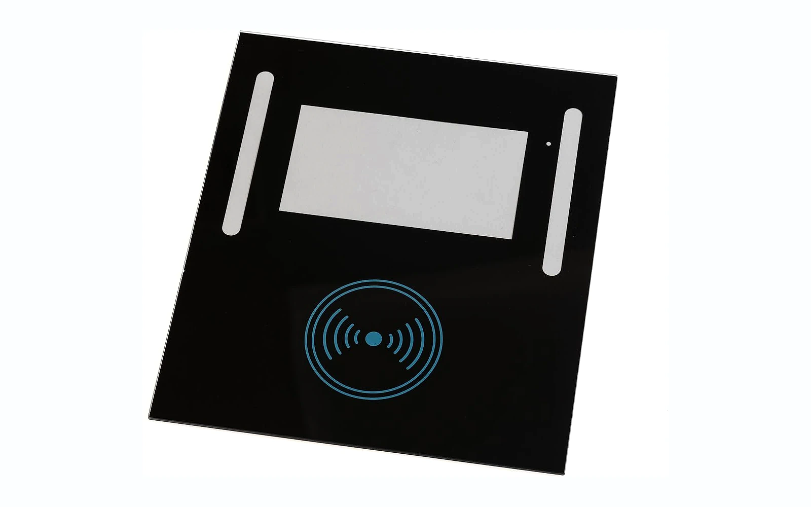

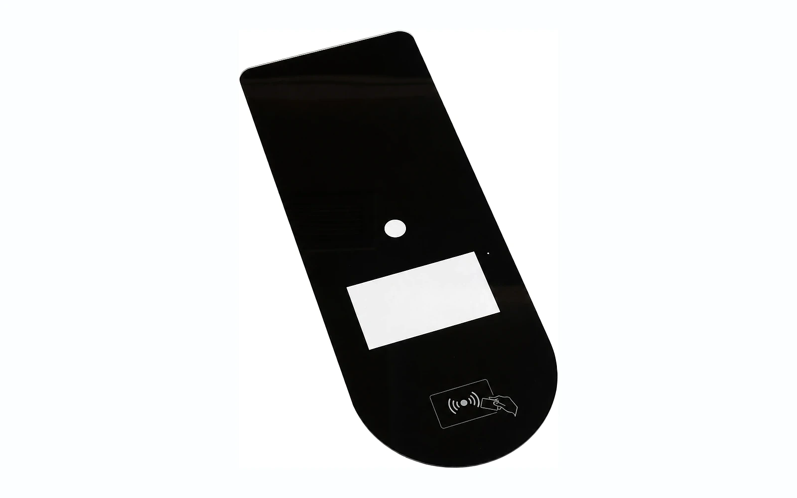


An EV charger glass panel can provide the customer-facing surface for a display, status indicators, touch controls, RFID or contactless-payment graphics and brand elements. It may also help protect the interface from repeated cleaning and public use. However, the glass is only one part of the charger enclosure.
Outdoor exposure, impact resistance, sealing, electrical safety and vandal resistance depend on the complete assembly: glass, frame, gasket or adhesive, housing, fasteners, display and internal support. A responsible supplier should define what the fabricated glass can be inspected for and avoid claiming that a bare panel alone gives the finished charger an enclosure rating.
This guide helps charger manufacturers, equipment integrators, product engineers and procurement teams build a practical glass specification. It covers indoor wallboxes, commercial charging terminals and outdoor public interfaces without inventing one universal construction for all three.
Quick answer: what should an OEM specify for an EV charger glass panel?
An effective EV charger glass panel RFQ should define:
- Installation environment: indoor, sheltered outdoor or exposed outdoor.
- Enclosure architecture and the function of the glass.
- Base glass, nominal thickness and strengthening condition.
- Panel geometry, holes, cut-outs, edge finish, datums and tolerances.
- Display, indicator, RFID/NFC, camera and sensor windows.
- Powered-off color, printed graphics, opacity and backlit appearance.
- Reflectivity, glare, transmission, haze and fingerprint or cleanability targets where required.
- Mounting method, adhesive, gasket, frame flatness and sealing concept.
- Impact, environmental, chemical, optical and assembly validation.
- Inspection conditions, traceability, approved samples and export packaging.
The enclosure designer should determine the applicable market standards and ratings. Validate the panel in the production-intent charger assembly rather than extrapolating from a bare-glass test.
1. Classify the installation environment
The phrase “EV charger” covers very different products. Begin by defining where and how the interface will be used.
Indoor residential wallbox
An indoor wallbox may face regular finger contact and household cleaning but limited direct weather. Appearance, touch behavior, display readability and compact mounting may be priorities.
Sheltered commercial charger
A charger under a canopy can still experience temperature variation, humidity, dust, repeated public use and stronger cleaning chemicals. Maintenance procedures and impact exposure should be stated.
Exposed outdoor charger
An outdoor public terminal may be exposed to sun, rain, condensation, freezing conditions, heat, pollutants, abrasion and vandalism. The glass, printing, coating, adhesive, gasket and enclosure should be validated as one system.
Document:
- Intended geographic markets.
- Temperature and humidity conditions used for design.
- UV and weather exposure.
- Cleaning agents and frequency.
- Expected impact or misuse scenarios.
- Mounting orientation and drainage.
- Display brightness and ambient-light range.
These requirements guide material, print, coating and test decisions. Avoid copying an “outdoor-grade” label without a measurable validation plan.
2. Define the role of the glass in the enclosure
The panel may be:
- A bonded cover over a display.
- A printed fascia installed into a metal or plastic frame.
- A decorative door panel.
- A touch-control interface.
- A cover for an RFID/NFC or payment zone.
- A combined display and status-light surface.
Provide a cross-section showing the glass, frame, seal, adhesive, display and support. State whether the edge is exposed and whether the panel contributes structurally to the enclosure.
SCHOTT’s EV-charger panel examples highlight design options such as shaped edges, multicolor printing, hidden displays and transmission windows for interface functions. These are useful design possibilities, but the required construction still depends on the OEM’s charger architecture and validation.
Do not assign enclosure performance to the glass alone
IEC 62262 defines the IK code used to classify protection provided by electrical equipment enclosures against external mechanical impacts. The code applies to the enclosure. A bare glass impact result does not automatically establish an IK rating for the finished charger.
If an OEM targets a particular enclosure classification, test the production-intent assembly with the correct frame, gasket, adhesive, fasteners and support. Record the tested revision and impact locations.
3. Select substrate, thickness and strengthening condition
Possible substrates include clear, low-iron, tinted or customer-specified glass. Selection factors include:
- Panel dimensions and unsupported span.
- Edge exposure.
- Holes and cut-outs.
- Mounting method.
- Required display color neutrality.
- Impact and misuse conditions.
- Thermal gradients from sun and electronics.
- Weight and service handling.
Low-iron glass can improve color neutrality for displays or light-colored graphics. Tinted glass can contribute to concealment but reduces transmission. A coating may adjust reflection or display behavior, but it adds its own durability and orientation requirements.
Thickness and strengthening should be selected with the complete enclosure. The supplier can review manufacturability and component options; the OEM should validate the assembled charger against its product requirements.
Complete all cutting, drilling and edge processing before full tempering. This makes early DFM review essential.
4. Design geometry for fabrication and assembly
The controlled drawing should define:
- Overall length, width and thickness.
- Corner radii and shaped profiles.
- Holes, slots, notches and sensor openings.
- Edge profile and visible zones.
- Assembly datums.
- Display and printed-window positions.
- Registration tolerances.
- Flatness or bow requirements where functionally necessary.
Use common datums between the glass, housing and display. If the display and glass window are located from different reference edges, accumulated tolerance can create an obvious visual mismatch.
Review edge risk
Public-facing equipment often has exposed or semi-exposed edges. Identify:
- Touchable edges.
- Corners at user height.
- Edges near screws or clips.
- Service-handling areas.
- Drainage or seal transitions.
The edge finish may be seamed, ground, polished, beveled or shaped according to the design. Define acceptance by zone and protect edges from direct hard contact.
Review fragile features
Ask the fabricator to comment on narrow bridges, tight internal radii, holes near edges and complex profiles. Adjusting a radius before tooling is released is easier than explaining breakage during pilot assembly.
5. Engineer display and indicator windows
An EV charger interface must remain understandable in varied ambient light. The glass specification should distinguish the powered-off appearance from the active display requirement.
Powered-off appearance
Define:
- Black, gray, mirror or another target color.
- Visibility of the display outline.
- Gloss and reflection.
- Permanent graphics.
- Acceptable contrast between windows and surrounding mask.
Display readability
Evaluate:
- Display brightness through the glass.
- Color shift.
- Contrast.
- Viewing angle and user height.
- Uniformity.
- Direct-sun and night-time readability.
- Internal reflection and double images.
Anti-reflective, anti-glare and anti-fingerprint functions
These terms describe different goals:
- Anti-reflective solutions aim to reduce surface reflection.
- Anti-glare surfaces diffuse reflection but may affect sharpness or sparkle.
- Anti-fingerprint or easy-clean treatments aim to reduce visible marks or improve cleaning.
Do not combine them into one vague requirement. Define the functional target, measurement method, surface orientation and durability exposure. Evaluate display resolution and appearance after the proposed treatment.
6. Specify printing and hidden-interface effects
Printed layers may:
- Mask adhesive and the frame.
- Define the display window.
- Carry charging-status icons.
- Show RFID or contactless-payment location.
- Provide instructions and warning symbols.
- Create a hidden-until-lit effect.
- Support brand color.
Provide controlled vector artwork with:
- Print side and viewing direction.
- Layer sequence.
- Color references.
- Opaque and semi-transparent zones.
- Indicator windows.
- RFID/NFC, infrared or sensor areas.
- Adhesive and seal keep-out areas.
- Registration tolerances.
For public equipment, confirm that required labels remain readable after the defined environmental and cleaning exposure. Where legal or market-specific labels are involved, the OEM should control content and language.
Validate radio and optical windows
RFID/NFC, infrared receivers, cameras and ambient-light sensors have different transmission needs. A window that looks suitable to the eye may affect a sensor. Define the technology, frequency or wavelength where relevant, material stack and test method.
The glass supplier can manufacture the window and perform agreed component checks. The equipment manufacturer should validate the complete reader, antenna or sensor behind the production-intent glass and housing.
7. Design mounting, sealing and installation preparation
The mounting system can determine whether a strong panel performs reliably.
For a bonded panel, control:
- Adhesive family and approved surface preparation.
- Bond-line geometry and thickness.
- Cure conditions.
- Primer where applicable.
- Continuous or segmented bead design.
- Drainage and moisture path.
- Rework or service procedure.
For gasketed or mechanically retained panels, control:
- Gasket material, hardness and compression.
- Frame flatness.
- Clip position and load.
- Fastener torque and isolation.
- Allowance for dimensional and thermal movement.
During installation preparation, verify the frame is clean, flat and free from burrs. The glass should not be twisted into an out-of-square opening or loaded by a point contact. Protective film should not interfere with bonding.
Sealing performance belongs to the complete assembly. Test the production-intent glass, frame, seal and process rather than assuming that an adhesive data sheet proves charger-level weather resistance.
8. Build a risk-based validation plan
The exact plan depends on the installation environment and target markets. A useful matrix separates component inspection from enclosure validation.
Glass component checks
Factory inspection may include:
- Dimensions and feature positions.
- Thickness.
- Edge and corner quality.
- Print color, opacity and registration.
- Window transmission or haze.
- Coating appearance or performance.
- Cosmetic inspection by defined zones.
- Batch and revision traceability.
Optical and interface checks
Using the production-intent display and sensors, evaluate:
- Powered-off concealment.
- Display readability across ambient-light conditions.
- Viewing angle.
- Indicator color and uniformity.
- Touch response.
- RFID/NFC or sensor operation.
- Night-time glare.
Mechanical and enclosure checks
Depending on product requirements:
- Assembly stress and frame distortion.
- External impact on the complete enclosure.
- Door or service cycling.
- Cable or internal component pressure.
- Vibration associated with transport or installation.
Environmental and chemical checks
Depending on the target environment:
- Temperature and humidity cycling.
- Condensation.
- UV or accelerated weathering.
- Water and dust tests at enclosure level.
- Cleaning chemicals.
- Abrasion and repeated wiping.
- Salt or pollutant exposure where relevant.
Use the OEM’s confirmed test conditions. Avoid presenting generic laboratory numbers as universal requirements.
9. Establish appearance inspection for public-facing equipment
An EV charger fascia is a large visible surface. Define a reproducible cosmetic method:
- Lighting and background.
- Viewing distance and angle.
- Inspection time.
- Critical display, graphic and edge zones.
- Scratch, inclusion, pinhole and print-defect limits.
- Protective-film condition.
- Approved master and boundary samples.
Inspect dark panels with representative backing and ambient light. A window may be hidden in one room and visible in direct sunlight. A coating may show non-uniformity only at an oblique angle.
Shipment inspection should confirm part number, drawing and artwork revision, quantity, dimensional status, appearance, labels and packaging. Link records to the production batch.
10. Approve samples in controlled stages
Engineering sample
Confirm glass geometry, edgework, holes, housing fit and basic print registration.
Optical and interface sample
Use the intended display, light guides, RFID/NFC reader and backing to approve powered-off and powered-on behavior.
Environmental and functional sample
Build production-intent assemblies for the OEM’s impact, weather, temperature, cleaning and interface tests.
Pilot production
Use production fixtures, print screens, inspection methods, bonding or gasket process and export packaging. Confirm repeatability before mass-production release.
Document every approval against a revision. If the display, adhesive, frame, glass, coating or artwork changes, assess whether the validation evidence remains applicable.
11. Plan export packaging and line-side handling
Large black glass panels show abrasion and edge damage easily. Packaging should protect both the cosmetic face and edge.
Define:
- Interleaving or protective film.
- Edge and corner protection.
- Orientation inside the pack.
- Quantity and maximum pack weight.
- Pallet and moisture protection.
- Handling and stacking limits.
- Part, batch and revision labels.
Run a packing trial before commercial shipment. Consider how operators remove the panel without dragging one coated surface across another. Packaging that survives transport but damages the panel during unpacking is not successful.
EV charger glass panel RFQ checklist
Send:
- Controlled 2D drawing and assembly cross-section.
- Installation environment and target markets.
- Material, thickness and strengthening requirement.
- Vector print artwork and color references.
- Display and indicator specifications.
- RFID/NFC, infrared, camera or sensor information.
- Coating or optical-function targets.
- Mounting, adhesive, gasket and housing details.
- Environmental, impact, chemical and optical validation requirements.
- Prototype quantity and annual estimate.
- Inspection documents, packaging and destination.
Ask suppliers to return a DFM review, process proposal, optical assumptions, sample plan, inspection plan, change-control expectations and open questions.
FAQ
Can a glass supplier guarantee an IK rating for an EV charger panel?
An IK classification applies to the electrical equipment enclosure. A supplier can provide component information, but the production-intent charger assembly should be tested with its actual glass, frame, gasket or adhesive, fasteners and support.
Is tempered glass always required?
The material and strengthening condition should be selected from the panel geometry, mounting, impact exposure and applicable product requirements. The OEM should confirm the final construction through assembly-level validation.
How can display readability be improved outdoors?
Evaluate display brightness, window transmission, reflection, glare, viewing angle and ambient light as one system. A higher-transmission window alone may make the display outline more visible when powered off.
Can RFID or NFC operate through printed glass?
It may, depending on the radio system, glass, printing, coating, spacing and enclosure. Define the interface zone and validate the production-intent reader and antenna behind the complete panel stack.
What information is most important for a quotation?
The controlled drawing, assembly cross-section, environment, artwork, display and sensor requirements, mounting method, validation criteria, expected volume and destination are the most useful inputs.
Conclusion
An EV charger glass panel is a customer-facing part of an electrical enclosure and digital interface. Successful sourcing requires more than selecting dark tempered glass. The specification should connect environment, geometry, printing, display optics, sensors and mounting with enclosure-level validation.
The supplier should control component manufacturing and inspection. The charger OEM should define applicable ratings and validate the production-intent assembly. Staged samples, approved visual masters and documented change control create a reliable route to repeat production.
CTA: Request an EV charger glass panel review
Send Tairong your panel drawing, assembly cross-section, print artwork, display or sensor requirements, installation environment and expected volume. We can review the manufacturing information needed for sampling and quotation.
Primary CTA: Send Your Requirements
Related products: Custom EV charger panel glass
Related guide: How to evaluate appliance glass supplier quality control